carbontracks
Junior Member

 Offline Offline
Posts: 66
Thank You
-Given: 20
-Receive: 4
|
 |
« on: February 09, 2010, 01:26:03 13:26 » |
|
For a while I've been designing a control system for a high power solid state tesla coil which includes vital analog telemetry circuitry for monitoring its health. It will have to operate in close proximity to the coil, so EMI immunity has become a concern that I can't avoid any longer. I want to implement some sort of shielding enclosure, but for this application I don't think I need on of the expensive pre-made shielded enclosures. I've heard that cookie tins can make good substitutes. The board needs about 6"x6"x1.5" (15x15x4cm) of space. It will need two wires coming out for power, two for output, and three fiber cables for data. And since this is for a tesla coil, the spectrum of the EMI is quite different from that of the microwave and radio frequencies that shielding is usually designed to block.
So does anyone have some insight for me on some low-cost solutions for shielding?
Thanks in advance,
-Mike
|
|
|
|
|
 Logged
|
|
|
|
cncbasher
Junior Member
Offline
Posts: 90
Thank You
-Given: 107
-Receive: 51
|
|
« Reply #1 on: February 09, 2010, 07:01:12 19:01 » |
|
tin foil ( kitchen foil ) stuck to both sides of some cardboard , may be worth a try
i have done the same layering the tin foil and cardboard alternatley into 5 layers
|
|
|
|
|
Logged
|
|
|
|
oldvan
Senior Member
Offline
Posts: 372
Thank You
-Given: 154
-Receive: 107
If the van is a Rockin'...

|
|
« Reply #2 on: February 09, 2010, 07:34:38 19:34 » |
|
Prehaps enclose your board in copper or brass screen box forming a faraday cage.
Hobby & craft shop seems likey to have the screen.
|
|
|
|
|
Logged
|
Give a man a fish and you feed him for a day.
Teach a man to fish and he will sit around in a boat drinking beer all day.
|
|
|
carbontracks
Junior Member
Offline
Posts: 66
Thank You
-Given: 20
-Receive: 4
|
|
« Reply #3 on: February 10, 2010, 03:31:56 03:31 » |
|
tin foil ( kitchen foil ) stuck to both sides of some cardboard , may be worth a try
i have done the same layering the tin foil and cardboard alternatley into 5 layers
I suppose, foil would be a good way to at least test the idea before investing in a more robust solution. Ultimately I'll be looking for something solid that can provide mechanical support as well. Prehaps enclose your board in copper or brass screen box forming a faraday cage.
Hobby & craft shop seems likey to have the screen.
Is screen effective for lower frequency fields? I'm dealing with intense transients in the 30KHz to 300KHz range, and in close proximity. Wouldn't the fields just couple directly through the holes in the screen? |
|
|
|
« Last Edit: February 10, 2010, 03:35:22 03:35 by carbontracks »
|
Logged
|
|
|
|
oldvan
Senior Member
Offline
Posts: 372
Thank You
-Given: 154
-Receive: 107
If the van is a Rockin'...
|
|
« Reply #4 on: February 10, 2010, 05:14:16 05:14 » |
|
http://en.wikipedia.org/wiki/Faraday_cageField should tend to follow the outside of the screen.
|
|
|
|
|
Logged
|
Give a man a fish and you feed him for a day.
Teach a man to fish and he will sit around in a boat drinking beer all day.
|
|
|
solutions
Hero Member
Offline
Posts: 1825
Thank You
-Given: 660
-Receive: 905
|
|
« Reply #5 on: February 10, 2010, 06:47:50 06:47 » |
|
With the electric field levels on that thing, you can shield it with ten inches of mumetal or copper and still get yourself in major trouble with conducted EMI on the power leads, IMNHO.
If it were me, I'd run the telemetry off of a 9V battery, encase the whole thing in a grounded metal "Faraday Cage" box (ideally copper or aluminum), and use a TOSLINK or similar fiber cable system for the telemetry...with glass or plastic fiber runing through a tiny aperture in the enclosure, you get the EMI immunity PLUS the galvanic isolation that will keep you from cooking the electronics (or worse, yourself) at the other end.
|
|
|
|
|
Logged
|
|
|
|
carbontracks
Junior Member
Offline
Posts: 66
Thank You
-Given: 20
-Receive: 4
|
|
« Reply #6 on: February 10, 2010, 01:27:52 13:27 » |
|
With the electric field levels on that thing, you can shield it with ten inches of mumetal or copper and still get yourself in major trouble with conducted EMI on the power leads, IMNHO. Well there''s no way we'll be putting it in mumetal or something ridiculous like that. I wish, though. If it were me, I'd run the telemetry off of a 9V battery, encase the whole thing in a grounded metal "Faraday Cage" box (ideally copper or aluminum), and use a TOSLINK or similar fiber cable system for the telemetry...with glass or plastic fiber runing through a tiny aperture in the enclosure, you get the EMI immunity PLUS the galvanic isolation that will keep you from cooking the electronics (or worse, yourself) at the other end.
There's no way it can be completely isolated. It will need around 5W of power at 48V, so there's no way we'll fit the power source inside the enclosure. And its outputs are power to drive the primary coil, so that can't be fiber. And for the various measurements (temperature, primary current, rail voltage), even if those were isolated, then the sensors would still need to have EMI-resistant design so that wouldn't really solve the problem. Some of these signals are ground referenced, so I'll be able to run them through coax with the shield conductor connected to the enclosure, which should work well. Its the other stuff I'm concerned about. I've heard about devices called feed-through filters which allow signals of certain bands to pass while shunting others. However, I'm not sure whether any of them can permit DC signals, which would make things easier. |
|
|
|
|
Logged
|
|
|
|
oldvan
Senior Member
Offline
Posts: 372
Thank You
-Given: 154
-Receive: 107
If the van is a Rockin'...
|
|
« Reply #7 on: February 10, 2010, 02:15:59 14:15 » |
|
A box made of copper-clad circuit board soldered at the edges might be a practical way to keep the noise out, following the idea used here: 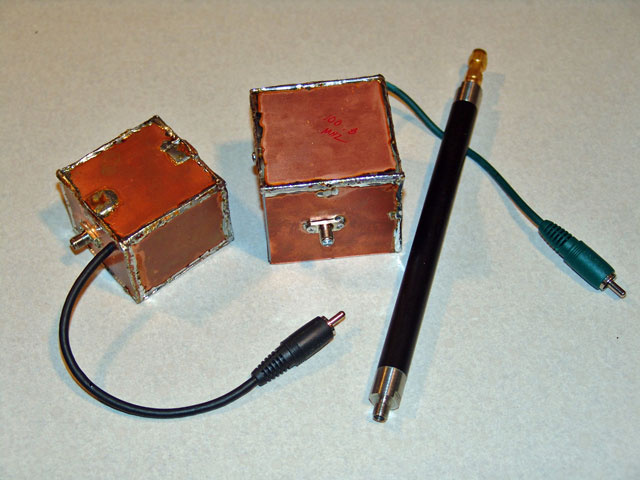 Feedthrough caps are definitely your friend here. From: http://www.hobbyprojects.com/electronics_component_symbols/what_is_feedthrough_capacitor.html"Feed through capacitors are originally designed for DC power line in RF module or system. It passed through the DC (and low frequency signals) but blocks the RF energy. In practical use the: feed through capacitors are fitted to the metal case of the RF module on holes where the wires enter the system. They let the signal pass through but will stop the RF from escaping from the device through that hole to the outside wiring."  Digikey has a good selection available. |
|
|
|
|
Logged
|
Give a man a fish and you feed him for a day.
Teach a man to fish and he will sit around in a boat drinking beer all day.
|
|
|
carbontracks
Junior Member
Offline
Posts: 66
Thank You
-Given: 20
-Receive: 4
|
|
« Reply #8 on: February 11, 2010, 01:47:07 01:47 » |
|
The copper clad shield looks promising, and I have a bunch of single sided copper clad lying around. The only drawback is that I'll need to open the enclosure fairly often, so it wouldn't be good for the main board, but it might be perfect for the current transformers located outside the main enclosure. Do you use some kind of foil to seal the edges, or is it just done with tons of solder?
Also, for the feedthrough capacitors, they aren't actually capacitors, correct? Otherwise they certainly wouldn't pass DC. So why are they called feedthrough capacitors?
|
|
|
|
|
Logged
|
|
|
|
oldvan
Senior Member
Offline
Posts: 372
Thank You
-Given: 154
-Receive: 107
If the van is a Rockin'...
|
|
« Reply #9 on: February 13, 2010, 06:52:59 06:52 » |
|
Lots of solder along the seams. This should clear up feedthrough capacitors for you: Feedthrough -vs- conventional capacitor:  Two leads of a feedthrough capacitor are actually the same wire, ground for the cap is the casing. |
|
|
|
« Last Edit: February 13, 2010, 06:55:12 06:55 by oldvan »
|
Logged
|
Give a man a fish and you feed him for a day.
Teach a man to fish and he will sit around in a boat drinking beer all day.
|
|
|
carbontracks
Junior Member
Offline
Posts: 66
Thank You
-Given: 20
-Receive: 4
|
|
« Reply #10 on: February 14, 2010, 06:19:05 18:19 » |
|
Lots of solder along the seams. This should clear up feedthrough capacitors for you: Feedthrough -vs- conventional capacitor: Two leads of a feedthrough capacitor are actually the same wire, ground for the cap is the casing. Ah I see, so the interleaving between the conductor and the shield prevents fields from getting through. I found some 1/32" FR4 copper clad which should be easy to make into small shields for my current transformers. Still looking for something to house the main board, though. |
|
|
|
|
Logged
|
|
|
|
oldvan
Senior Member
Offline
Posts: 372
Thank You
-Given: 154
-Receive: 107
If the van is a Rockin'...
|
|
« Reply #11 on: February 14, 2010, 09:51:45 21:51 » |
|
How big is the main board?
|
|
|
|
|
Logged
|
Give a man a fish and you feed him for a day.
Teach a man to fish and he will sit around in a boat drinking beer all day.
|
|
|
carbontracks
Junior Member
Offline
Posts: 66
Thank You
-Given: 20
-Receive: 4
|
|
« Reply #12 on: February 14, 2010, 11:48:18 23:48 » |
|
The board is 6"x"6x1", and will have three fibers and around a dozen wires coming out of it.
|
|
|
|
|
Logged
|
|
|
|
oldvan
Senior Member
Offline
Posts: 372
Thank You
-Given: 154
-Receive: 107
If the van is a Rockin'...
|
|
« Reply #13 on: February 15, 2010, 01:26:01 01:26 » |
|
Perhaps a box made of copper clad but with the top secured with screws instead of soldered, paying extra attention to making sure copper contacts copper all around?
Knowing the level of noise the board will live in, and the need to be able to open the box, I'd be inclined to use 8" squares of 1/4" aluminum plate for top and bottom. A 8" square frame made of 1/2" by 2" aluminum stock for the sides, drilled and tapped to accept a dozen 1/4" cap screws per plate.
This may be overkill, but it should offer extremely effective shielding and gives a cool machine shop / industrial look.
Where are you located? I may be in a position to lend some sort of help if you are interested.
|
|
|
|
|
Logged
|
Give a man a fish and you feed him for a day.
Teach a man to fish and he will sit around in a boat drinking beer all day.
|
|
|
thecic
Newbie
Offline
Posts: 12
Thank You
-Given: 1
-Receive: 8
|
|
« Reply #14 on: February 16, 2010, 01:44:56 01:44 » |
|
Are you doing the kind of Tesla coils that send arcs into the air then it won't help so much if you protect the electronics, the arcs emits horrible RF garbage, or have I misunderstood your post?
|
|
|
|
|
Logged
|
|
|
|
carbontracks
Junior Member
Offline
Posts: 66
Thank You
-Given: 20
-Receive: 4
|
|
« Reply #15 on: February 17, 2010, 01:48:40 13:48 » |
|
Where are you located? I may be in a position to lend some sort of help if you are interested.
I'm in cleveland. We have access to a machine shop and plenty of material, so resources aren't that much of an issue. Just the design. Thanks for the offer, though. Are you doing the kind of Tesla coils that send arcs into the air then it won't help so much if you protect the electronics, the arcs emits horrible RF garbage, or have I misunderstood your post?
Yeah, it's a musical SSTC, so it will be putting out arcs (over ten feet hopefully). The worst source of noise is definitely going to be from the actual sparks, but that's entirely comprised of E fields, so it should be possible to shield the electronics effectively. |
|
|
|
« Last Edit: February 17, 2010, 01:51:37 13:51 by carbontracks »
|
Logged
|
|
|
|
|


