Manuel
Senior Member

 Offline Offline
Posts: 353
Thank You
-Given: 794
-Receive: 206
|
 |
« on: January 11, 2019, 08:19:07 08:19 » |
|
Hi you All,
I am having a nice issue using a 12V 2A switching power supply.
The issue is present at every first load contact, then the power supply properly anyway.
Here I describe the way to catch the issue:
-the power supply is already connected to the MAIN AC line and is delivering the 12Vdc on the Low voltage side. It seems to work correctly.
-in the moment I connect this power supply to my light load (tantalium capacitive load of 1uF (1.6ohm)) the voltage drop up to 5V and then recover quickly creating a voltage overshoot up to 20.8V. This event takes few microseconds. (here I attach a picture of the even just as example (it reach 18.9v this time))
-The issue is : voltage regulator on the electronic load are often destroyed since the voltage regulator has got a Vmax rated up to 18V.
I am not expecting that a switching power supply work in this way.....do you have any hint?
take care,
Xo!
|
|
|
|
|
 Logged
|
-> An Apple a Day does not Let U become a Macintosh!
|
|
|
pickit2
Moderator
Hero Member
 Offline
Posts: 4684
Thank You
-Given: 859
-Receive: 4460
There is no evidence that I muted SoNsIvRi
|
 |
« Reply #1 on: January 11, 2019, 03:14:56 15:14 » |
|
Do you have long power lead? sounds like a problem caused by lead inductance.
screen shows power fed into a short, then a fast recover, so over shooting.
you get this effect when powering up loudspeakers term used to correct it is called Slow Start up.
I seen such a problem solved with another capacitor and Diode.
Edit: change the tantalium as they have a Low ESR, you need a higher ESR.
|
|
|
|
« Last Edit: January 11, 2019, 03:26:46 15:26 by pickit2 »
|
Logged
|
Note: I stoped Muteing bad members OK I now put thier account in sleep mode
|
|
|
PM3295
Senior Member
Offline
Posts: 317
Thank You
-Given: 365
-Receive: 157
|
|
« Reply #2 on: January 11, 2019, 03:44:21 15:44 » |
|
Is this an off-the-shelf power supply or your own design? The oscillating recovery can also be due to a bad control loop with insufficient phase margin. Do a load step with a pure resistive load and see if the recovery is any better.
|
|
|
|
|
Logged
|
|
|
|
optikon
Cracking Team
Hero Member
Offline
Posts: 861
Thank You
-Given: 1139
-Receive: 2008
|
|
« Reply #3 on: January 11, 2019, 10:00:42 22:00 » |
|
Also, the tantalum cap might not seem like too large of a value but it might also be contributing to a startup surge.
What is its voltage rating? Generally, tantalums should have some impedance upstream of them to avoid possibly failing short due to an inherent dV/dt kind of limit.
Significant voltage de-rating and a little bit of impedance is often the cure *if this is your issue*
You can try easy experiment, try adding ~ 0.5 Ohms in series with your cable and see it helps the start up issue. If you see the issue improve, its not a good solution but it can indicate thats the problem.
Alternatively, change the tantalum with an aluminum electrolytic of similar value. It will have a higher ESR.
|
|
|
|
|
Logged
|
I can explain this to you. I can't comprehend it for you.
|
|
|
Signal
Active Member
Offline
Posts: 199
Thank You
-Given: 113
-Receive: 81
|
|
« Reply #4 on: January 12, 2019, 07:13:27 07:13 » |
|
There is nothing wrong with control loop. As pickit2 said this transient definitely caused by inductance. Just normal transient of passive circuit you can look at thanks to modern capturing oscilloscope. Here is the model with similar behavior. Note how capacitance influences on overshoot. 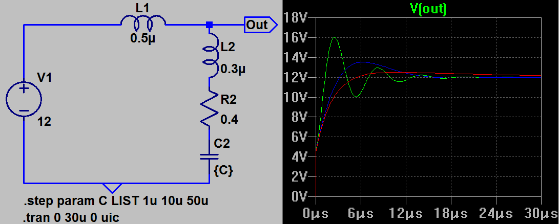 |
|
|
|
|
Logged
|
Give a right name to a right game and play it right
|
|
|
Manuel
Senior Member
Offline
Posts: 353
Thank You
-Given: 794
-Receive: 206
|
|
« Reply #5 on: January 12, 2019, 08:09:01 08:09 » |
|
Thank you to you all first of all !
Power lead length is 2000mm, but same issue is present with a length of 1000mm.
The same issue is present using 4.7uF ceramic capacitor.
Personally I think it is missing a proper output filtering from the switching power supply.
So, almost all your writings are good, to be honest what I underline is the following:
- if you use components suitable to work up to 18V do not expect that nothing can happen connecting a 12V switching power supply to them...
I think that the cheapest solution is to use different components in general, and remember: end users are allowed to use often their own power supplies, so you can not control how good are Vout filtering from those.
Anyhow, there are also other considerations that can be done: does a spike of 2us up to 20.8V will destroy a component that has 18V as absolute maximum rating ?
Thank you so Much !
take care,
Xo.
|
|
|
|
« Last Edit: January 12, 2019, 08:14:58 08:14 by Manuel »
|
Logged
|
-> An Apple a Day does not Let U become a Macintosh!
|
|
|
Signal
Active Member
Offline
Posts: 199
Thank You
-Given: 113
-Receive: 81
|
|
« Reply #6 on: January 12, 2019, 09:03:58 09:03 » |
|
Power lead length is 2000mm, but same issue is present with a length of 1000mm.
so a couple of uH is yours. Try to measure. The same issue is present using 4.7uF ceramic capacitor.
Is it difficult to check 100uF, 220uF...? Why do you think 4.7uF is enough? Any calculations? Personally I think it is missing a proper output filtering from the switching power supply.
<...> and remember: end users are allowed to use often their own power supplies, so you can not control how good are Vout filtering from those.
I see a contradiction in these sentences (or I've lost in translation). Actually the _input_ filter of your device is missing (or at least not sufficient) for given conditions. Can you explain the level of drop to 5V you measured? How can you _think_ further without answering on the question about "what's going on"? Anyway there is still uncertainty about configuration of measurement you make. |
|
|
|
|
Logged
|
Give a right name to a right game and play it right
|
|
|
Sideshow Bob
Cracking Team
Hero Member
Offline
Posts: 1082
Thank You
-Given: 239
-Receive: 1058
|
|
« Reply #7 on: January 12, 2019, 09:25:44 09:25 » |
|
What is your load. Is it some commercial device or is it something you have made by your self. Also what kind of power do it draw
|
|
|
|
|
Logged
|
I have come here to chew bubblegum and kick ass... and I'm all out of bubblegum
|
|
|
Signal
Active Member
Offline
Posts: 199
Thank You
-Given: 113
-Receive: 81
|
|
« Reply #8 on: January 12, 2019, 11:39:12 11:39 » |
|
On picture I previously posted an "Out" is a supposed connection point of oscilloscope probe. At R2 a voltage spike is higher.
In some of my low power devices to be connected to vehicle's 12/24V battery line I use serial Anti-Pulse serial resistor (3.9 Ohm) before 30 - 50 uF capacitance at voltage regulator's input. Of course, in case you need 2A this solution is not suitable and should be modified. For example by adding serial resistor not in serial with input but in serial with input capacitor (or to add RC snubber in parallel to input C).
pickit2 already suggested that you need higher ESR, Manuel. You, instead, change to ceramic capacitor with even lower ESR. Why to ask if then not to listen?
|
|
|
|
|
Logged
|
Give a right name to a right game and play it right
|
|
|
vern
V.I.P
Active Member
 Offline
Posts: 147
Thank You
-Given: 7
-Receive: 42
|
|
« Reply #9 on: January 12, 2019, 11:46:20 11:46 » |
|
This has nothing to do with cable length, filtering etc, there is definitely something wrong with the control loop or maybe a missing or broken output cap.
What kind of power supply is it? Off-the-shelf power supply or your own design?
Did you try and put a larger cap (like several 100uF) to the output? That would stabilize the control loop.
To SIGNAL: in your diagram L1 should be more like 3uH with 2m cable and of course there must be a similar one in the - line.
|
|
|
|
|
Logged
|
|
|
|
pickit2
Moderator
Hero Member
Offline
Posts: 4684
Thank You
-Given: 859
-Receive: 4460
There is no evidence that I muted SoNsIvRi
|
|
« Reply #10 on: January 12, 2019, 11:54:18 11:54 » |
|
Another point you say the Voltage Regulator gets fried.
What Device? Please don't say a 7805
What extra Protection?
We are looking into a fog of mist.
|
|
|
|
|
Logged
|
Note: I stoped Muteing bad members OK I now put thier account in sleep mode
|
|
|
optikon
Cracking Team
Hero Member
Offline
Posts: 861
Thank You
-Given: 1139
-Receive: 2008
|
|
« Reply #11 on: January 12, 2019, 01:06:53 13:06 » |
|
Thank you to you all first of all !
...
Anyhow, there are also other considerations that can be done: does a spike of 2us up to 20.8V will destroy a component that has 18V as absolute maximum rating ?
After repeated applications of power up spikes, I would say YES quite possibly it will damage / destroy in the long run. It is an electrical over-stress for the component. If in the end, its a poor converter design -- then change it. No use keeping junk designs around. If on the other hand you HAVE to live with it.. then perhaps you can use higher voltage rated components or add some clamping protection like TVS diodes, series R-C, zener diode etc... or do both. |
|
|
|
|
Logged
|
I can explain this to you. I can't comprehend it for you.
|
|
|
Sideshow Bob
Cracking Team
Hero Member
Offline
Posts: 1082
Thank You
-Given: 239
-Receive: 1058
|
|
« Reply #12 on: January 12, 2019, 02:12:51 14:12 » |
|
It could also be that your test load is to light. You could introduce a bleed resistor to closer mimic your real load. And also we are not sitting next to you on your workbench so we know nothing about your setup. Instead of giving information drip by drip. Put ALL relevant information on the table
|
|
|
|
|
Logged
|
I have come here to chew bubblegum and kick ass... and I'm all out of bubblegum
|
|
|
zokij
Senior Member
Offline
Posts: 350
Thank You
-Given: 272
-Receive: 700
Nice time :)
|
|
« Reply #13 on: January 12, 2019, 03:17:17 15:17 » |
|
Manuel,
What 12V 2A switching power supplay do you use?
that it might not be a 2V 2A switching power supplay battery charger?
for 2V 2A switching power supplay battery charger its all what you write normal when you connect other then battery...
probably you should check is it charger...
|
|
|
|
|
Logged
|
|
|
|
Manuel
Senior Member
Offline
Posts: 353
Thank You
-Given: 794
-Receive: 206
|
|
« Reply #14 on: January 12, 2019, 04:18:33 16:18 » |
|
What a Nice Mess is growing up....
I will explain you all tomorrow, since I am away today.
Voltage regulator was: MCP1703 at 3.3V SOT23-3: in my project just such type of product can be used, since it's small, efficient and really with low noise. A common 78L03 can not be used because too noisy.
5 different switching low cost power supplies from chinese market, all are working correctly, all expose same issue. CUI and MEANWELL does not expose this issue.....
I will give you further detail tomorrow...
take care,
Xo!
|
|
|
|
|
Logged
|
-> An Apple a Day does not Let U become a Macintosh!
|
|
|
vern
V.I.P
Active Member
Offline
Posts: 147
Thank You
-Given: 7
-Receive: 42
|
|
« Reply #15 on: January 12, 2019, 07:48:00 19:48 » |
|
What are you talking about? Now I understand absolutely nothing. What is it, Mains to 12V, or 12 to 3.3V or what?
|
|
|
|
|
Logged
|
|
|
|
Manuel
Senior Member
Offline
Posts: 353
Thank You
-Given: 794
-Receive: 206
|
|
« Reply #16 on: January 12, 2019, 07:50:42 19:50 » |
|
Mains to 12Vdc,
then connected to an electronic that use V-REG to reduce voltage for processor side to 3.3V.
take care,
Xo!
|
|
|
|
|
Logged
|
-> An Apple a Day does not Let U become a Macintosh!
|
|
|
bigtoy
Active Member
Offline
Posts: 238
Thank You
-Given: 365
-Receive: 297
|
|
« Reply #17 on: January 13, 2019, 12:43:01 00:43 » |
|
It's so hard to tell what's going on, from the little information you've provided here. The comments above are valid.
Most power supplies are designed to power a resistive load, at a decent percentage of their rated power. If your load is very light, and capacitive & inductive, the PSU will struggle with it. A simple test is to put a resistive load right on the output of the power supply. It needs to be a decent sized resistive load, ie, something that will draw 10% or 20% of the PSU's rated current. A 10k resistor's probably not going to do it! :-) That test will tell you a lot about the PSU's behaviour. With that kind of a load, you shouldn't see that output overshoot any longer. Then you can experiment to determine what kind of load is going to meet your requirements for your application.
|
|
|
|
|
Logged
|
|
|
|
Manuel
Senior Member
Offline
Posts: 353
Thank You
-Given: 794
-Receive: 206
|
|
« Reply #18 on: January 13, 2019, 10:35:06 10:35 » |
|
The light schematic is here attached.
Initial conditions:
-The power supply is connected to AC line (wall mount switching power supply).
-The DC will be connected to the here attached schematic.
-The DC channel is connected to the oscilloscope.
Event:
>>When DC is applied to this schematic here attached, the waveform from the DC side is the one I showed you in the very first post.
The DC side cable length is 1000mm.
The MOV was omitted in my testing, it is valid just for a 24Vdc (not this case).
The V-REG is connected to a 4.7uF capacitor an 100nF. (not present in the light schematic)
C4 tested with both 1uF and 4.7uF (unpolarized tantalium).
It is obvious the generated waveform....but personally not expected, since I would have inserted a TVS in the power supply to avoid such high vout at the first contact.
My Post is more a WARNING than an help request... but suggestions and hints are welcome..
take care,
Xo!
|
|
|
|
|
Logged
|
-> An Apple a Day does not Let U become a Macintosh!
|
|
|
pickit2
Moderator
Hero Member
Offline
Posts: 4684
Thank You
-Given: 859
-Receive: 4460
There is no evidence that I muted SoNsIvRi
|
|
« Reply #19 on: January 13, 2019, 12:37:55 12:37 » |
|
Just a quick reply
you said 'Voltage regulator was: MCP1703 at 3.3V SOT23-3
This is not a good device to use in your circuit as its main use is for battery powered devices.
the max input is only 16V not 18v so your close to limit
using a 12V wall wart is not a good thing as they have no regulation most give out 11 to 19 volts.
damn spelling.
|
|
|
|
« Last Edit: January 13, 2019, 12:45:25 12:45 by pickit2 »
|
Logged
|
Note: I stoped Muteing bad members OK I now put thier account in sleep mode
|
|
|
Manuel
Senior Member
Offline
Posts: 353
Thank You
-Given: 794
-Receive: 206
|
|
« Reply #20 on: January 13, 2019, 12:43:21 12:43 » |
|
Exactly !
The question is this: 12V wall wart is not a good thing as they have no regulation most jive out 11 to 19 volts.
Thank you pickit2!
take care,
Xo!
|
|
|
|
|
Logged
|
-> An Apple a Day does not Let U become a Macintosh!
|
|
|
b555b
Junior Member
Offline
Posts: 66
Thank You
-Given: 73
-Receive: 131
|
|
« Reply #21 on: January 13, 2019, 03:13:14 15:13 » |
|
The question is this: 12V wall wart is not a good thing as they have no regulation most jive out 11 to 19 volts.
This is especially true for noname eBay/AliExpress wall adapters. For serious things you must consider using wall adapters from renowned brands. A GST25E12 from MeanWell (12V/2A) for example is specified at 3% voltage/line/load regulation. Different specs, different price too... |
|
|
|
« Last Edit: January 14, 2019, 03:37:21 15:37 by b555b »
|
Logged
|
|
|
|
Signal
Active Member
Offline
Posts: 199
Thank You
-Given: 113
-Receive: 81
|
|
« Reply #22 on: January 14, 2019, 07:42:59 07:42 » |
|
Manuel, could you post the photo of power supply PCB? I am especially interested in output capacitor value.
|
|
|
|
|
Logged
|
Give a right name to a right game and play it right
|
|
|
Manuel
Senior Member
Offline
Posts: 353
Thank You
-Given: 794
-Receive: 206
|
|
« Reply #23 on: January 14, 2019, 07:54:36 07:54 » |
|
b555b, GS25E12 has been obsoleted... :-)
The question was not related to price, but to a technical issue rised due to no post protection/regulation on the DC channel of power supply.
Essentially: coupling contact create ONE spike with a value that is close to the power supply double for a time of 4us.
This was not expected.
So light electronic design will find issue using such power supplies.
pickit2 underline that a component with : Input Operating Voltage Range: 2.7V to 16.0V (with Absolute Maximum Ratings Vdd +18V), will be possibly affected..
My ideas was to use such a silly TVS product like SMF11A or a VREG with higher Voltage rating.
take care,
Xo!
|
|
|
|
|
Logged
|
-> An Apple a Day does not Let U become a Macintosh!
|
|
|
Signal
Active Member
Offline
Posts: 199
Thank You
-Given: 113
-Receive: 81
|
|
« Reply #24 on: January 14, 2019, 09:43:47 09:43 » |
|
I have some thoughts about linear regulator to 3 V powered by 12V.
1) Linear regulator (MCP1703) from 12V to 3.3V at 250mA radiates more that 2W. It is too much for sot23. (No requirements was stated for current limit so I took the maximum for MCP1703)
2) Serial resistor 30 Ohm before such regulator introduces additional 7.5V drop and radiates 1.875W at 250mA. Then linear regulator has only 0.3W to radiate that is already acceptable.
3) 1uF at MCP1703 input as noted in datasheet is placed near to regulator and needed for stability. (For some regulators the requirement of having input capacitance not less or bigger then output is explicitly noted.) It is not enough to effectively compensate big load transients though if there is no additional bulk capacitor near on PCB and device is powered by long/unspecified cable. Of course it depends on dropout reserve too.
4) I'd use at least 100uF right after serial input resistor. Then tau=3000us. So with 30 Ohm load there will be no such "first connection" drop and overshot or it will be effectively filtered out. Rapid change of load current will cause "line/input" level change slow enough to effectively regulate it.
5) If manufacturer states 18V as absolute maximum without specifying time conditions (or avalanche rating) then I consider it dies at 18V immediately without any optimistic assumptions. Although I know that the one that kills electronic devices is energy, not voltage.
6) if an input is exposed and power supply polarity is not guaranteed then reverse power protection is needed - at lease a diode.
My choice however for low power device is to use 2954 or 9036 (both with reverse polarity protection) as first step to get 5V followed by 1703. As a bonus - 3.3V will be cleaner. And of course I'd consider the use of 220VAC/5VDC power supply instead of 12V. But I do not know full requirements for given device.
|
|
|
|
« Last Edit: January 14, 2019, 10:35:08 10:35 by Signal »
|
Logged
|
Give a right name to a right game and play it right
|
|
|
|


