Ichan
Hero Member

 Offline Offline
Posts: 832
Thank You
-Given: 312
-Receive: 392

|
 |
« on: July 06, 2014, 09:11:42 21:11 » |
|
I need a small 12VDC to 220VAC 50 Hz sine wave inverter, 25 watt max is enough. Simple and low cost will be the priority, also there is dimension restriction of 40x40x80 mm max. The sine wave do not need to be pure, just close to is enough. One dilemma is between iron core vs ferrite core transformer (low vs high frequency converter). With iron core the circuit is simple but the transformer is big and bulky also more expensive, whilst with ferrite core the circuit becoming complex as the conversion done in several steps. Two i found on the web: http://www.m0ukd.com/electronics/modified_sine_wave_inverter/ - seems too simple and not "sine wave enough" (?). http://www.edaboard.com/thread248198-11.html#post1351486 - i am not sure the transformer used, seems iron core (?). Any though? Also, can i use three 10VA iron core transformer in parallel to get 30VA ? This is about dimension restriction. -ichan |
|
|
|
|
 Logged
|
There is Gray, not only Black or White.
|
|
|
titi
Active Member
Offline
Posts: 230
Thank You
-Given: 4121
-Receive: 834
|
|
« Reply #1 on: July 06, 2014, 11:03:23 23:03 » |
|
|
|
|
|
|
Logged
|
|
|
|
|
|
DreamCat
Senior Member
Offline
Posts: 283
Thank You
-Given: 223
-Receive: 116
|
|
« Reply #3 on: July 07, 2014, 11:50:49 11:50 » |
|
Hi Ichan, why not try to do it with the SPWM technoligy. It's not very hard to do it now. such as some type of mcu with four channel pwm output of stm8 family, or other family's mcu with enough pwm output and ADC. oh~~I saw the topic on edaboard which you past here. it is a SPWM. frequancy is 31250Hz. ferrite core transformer.  |
|
|
|
|
Logged
|
May be I expressed the wrong meaning, sorry for my bad english. Please correct it for me if you can.
|
|
|
Ichan
Hero Member
Offline
Posts: 832
Thank You
-Given: 312
-Receive: 392
|
|
« Reply #4 on: July 08, 2014, 09:44:01 21:44 » |
|
Thanks, seems it is similar with my first link but the web has some more info on this. No word on efficiency?
I have no idea using class D amplifier, the efficiency specified is not very high - 0.7 or more. why not try to do it with the SPWM technoligy. It's not very hard to do it now. such as some type of mcu with four channel pwm output of stm8 family, or other family's mcu with enough pwm output and ADC. oh~~I saw the topic on edaboard which you past here. it is a SPWM. frequancy is 31250Hz. ferrite core transformer. Yes, i am interested with this SPWM thing - do you have any other references? 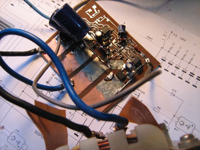 Are you sure about ferrite core transformer? The author mostly talk about 50 Hz transformer, and the photo also shows an iron core transformer (at the bottom of the photo above). I do really hope a ferrite transformer can be used as it will solve the dimension restriction. -ichan |
|
|
|
|
Logged
|
There is Gray, not only Black or White.
|
|
|
DreamCat
Senior Member
Offline
Posts: 283
Thank You
-Given: 223
-Receive: 116
|
|
« Reply #5 on: July 11, 2014, 10:33:08 10:33 » |
|
sorry, since GREAT FIRE WALL, It is very hard to access foreign these days. Are you sure about ferrite core transformer? The author mostly talk about 50 Hz transformer, and the photo also shows an iron core transformer (at the bottom of the photo above). I do really hope a ferrite transformer can be used as it will solve the dimension restriction.
In that link, there is a image:  the mcu output four channel PWM(SPWM) singal to drive MOSFET, the high-side through the 6N137. you may noticed, there is no transformer, only a big inductor(5mH), use as PFC with a 0.22uF capitor. the thing in the image which in your last post is a inductor, not a transformer, It only have two wire(black and blue). I don't know what size ferrite core is need to make a 5mH inductor. but I think it will be very large and expansive. LOL Posted on: July 11, 2014, 11:29:37 11:29 - Automerged
I decide to simulat the whole circuit except the mcu part. but, where is the 330V comes from? |
|
|
|
« Last Edit: July 11, 2014, 10:42:12 10:42 by DreamCat »
|
Logged
|
May be I expressed the wrong meaning, sorry for my bad english. Please correct it for me if you can.
|
|
|
pickit2
Moderator
Hero Member
 Offline
Posts: 4684
Thank You
-Given: 859
-Receive: 4459
There is no evidence that I muted SoNsIvRi
|
|
« Reply #6 on: July 11, 2014, 10:45:21 10:45 » |
|
I don't know what size ferrite core is need to make a 5mH inductor. but I think it will be very large and expansive. LOL A note in the circuit says it is from a PC Power Supply, so it will be free to most people.. |
|
|
|
|
Logged
|
Note: I stoped Muteing bad members OK I now put thier account in sleep mode
|
|
|
Ichan
Hero Member
Offline
Posts: 832
Thank You
-Given: 312
-Receive: 392
|
|
« Reply #7 on: July 11, 2014, 12:33:36 12:33 » |
|
Hi DreamCat, The schematic you refer to is the 300 VDC input version, my interest is on 12 VDC input. It is on post#204 with tiny13 or post#193 with stm8. -ichan |
|
|
|
|
Logged
|
There is Gray, not only Black or White.
|
|
|
DreamCat
Senior Member
Offline
Posts: 283
Thank You
-Given: 223
-Receive: 116
|
|
« Reply #8 on: July 21, 2014, 02:00:12 14:00 » |
|
Hi Ichan,
I saw both post, all of them are SMPS, but I am confused too. for the PWM signal that modulated by sine wave, which is the main component? 50Hz sine wave or 30kHz PWM(I only rememberd a few Fourier transformation)?
So I searched a lot of schematic about SPWM inverter, and I noticed most of them use iron core transformer, a few of them has no transformer or hase ferrite core transformer. Since you wish it is not very bulky, I recommand you choice the no transformer(transless) structure.
|
|
|
|
|
Logged
|
May be I expressed the wrong meaning, sorry for my bad english. Please correct it for me if you can.
|
|
|
sam_des
Senior Member
Offline
Posts: 259
Thank You
-Given: 138
-Receive: 161
|
|
« Reply #9 on: July 21, 2014, 05:54:10 17:54 » |
|
Hi Ichan, - If you want to use Ferrite Core Transformers, there is only one way,
12V-->DC-DC Converter (Output=+/-150VDC or +300VDC)-->Half Bridge/Full Bridge Inverter-->50 Hz Filter-->230VAC You need regulation at DC-DC stage as well as at inverter stage. Obviously circuit will neither be simple nor low cost.
- With 25W max output, I don't think iron-core transformer will be big. But no way it can fit within 40x40x80mm, may be just the control circuitry, without transformer.
- Also its not possible to connect 3 x 10VA transformers to get 30VA without proper syncing. Much simple if you use single 30VA transformer.
- For 50Hz output, LP filter at output is nearly always bulky, but that also depends on its power rating. With 25W(110mA) it won't be that big.
Do you really need sine wave ? What THD is acceptable ? Is push-pull inverter output (stepped sine wave/square wave) acceptable ? regards sam_des |
|
|
|
|
Logged
|
Never be afraid to do something new. Remember Amateurs built the Ark, Professionals built the Titanic !
|
|
|
sohel
Senior Member
Offline
Posts: 443
Thank You
-Given: 169
-Receive: 149
|
|
« Reply #10 on: July 23, 2014, 07:04:26 19:04 » |
|
Dear,
sample picture will help to understand. i think you need like that.
|
|
|
|
|
Logged
|
|
|
|
metal
Global Moderator
Hero Member
 Offline
Posts: 2419
Thank You
-Given: 862
-Receive: 678
Top Topic Starter
|
|
« Reply #11 on: July 24, 2014, 12:44:19 12:44 » |
|
were you the one who made this?
|
|
|
|
|
Logged
|
|
|
|
sohel
Senior Member
Offline
Posts: 443
Thank You
-Given: 169
-Receive: 149
|
|
« Reply #12 on: July 24, 2014, 01:20:51 13:20 » |
|
were you the one who made this?
it was a prototype which design by me. |
|
|
|
|
Logged
|
|
|
|
DreamCat
Senior Member
Offline
Posts: 283
Thank You
-Given: 223
-Receive: 116
|
|
« Reply #13 on: July 26, 2014, 06:54:01 06:54 » |
|
Dear,
sample picture will help to understand. i think you need like that.
have two H bridge? |
|
|
|
|
Logged
|
May be I expressed the wrong meaning, sorry for my bad english. Please correct it for me if you can.
|
|
|
Ichan
Hero Member
Offline
Posts: 832
Thank You
-Given: 312
-Receive: 392
|
|
« Reply #14 on: August 03, 2014, 12:18:58 12:18 » |
|
Thanks to all who give their words, but as the chance to get this project is getting smaller then i decide to put in on bottom stack of my priority for now  . Solutions buddy usually complaint if the OP did not tell the real application of the question, so here is some description. It is a small UPS for 220VAC 18Watt TL LED lamp, the circuit and the battery (NiMH) need to be fit on the lamp housing - this kind of device required on standard safety of high rise buildings - all lamp on emergency exit path need to have a backup power. I do have a sample of commercial product on my hand, it is a "conventional" dual conversion type - too complicated and expensive for it's usage in my thought. But it is now on my bench drawer  . -ichan |
|
|
|
|
Logged
|
There is Gray, not only Black or White.
|
|
|
zac
Active Member
Offline
Posts: 153
Thank You
-Given: 82
-Receive: 57
|
|
« Reply #15 on: August 11, 2014, 05:35:52 17:35 » |
|
It is a small UPS for 220VAC 18Watt TL LED lamp, the circuit and the battery (NiMH) need to be fit on the lamp housing - this kind of device required on standard safety of high rise buildings - all lamp on emergency exit path need to have a backup power
If you're providing backup power to an LED lamp, wouldn't it be simpler and more energy efficient to do the backup in DC mode and skip the inverter by using an LED lamp that can run from DC? |
|
|
|
|
Logged
|
|
|
|
Ichan
Hero Member
Offline
Posts: 832
Thank You
-Given: 312
-Receive: 392
|
|
« Reply #16 on: August 13, 2014, 04:19:26 16:19 » |
|
If you're providing backup power to an LED lamp, wouldn't it be simpler and more energy efficient to do the backup in DC mode and skip the inverter by using an LED lamp that can run from DC?
That is very true, the best place to put the backup power is on the led driver circuit itself. But on this project, that part (led + driver) already taken by the big player - what i can think of is to add a kind of add on module to their product without modifying it. -ichan. |
|
|
|
|
Logged
|
There is Gray, not only Black or White.
|
|
|
alien
Junior Member
Offline
Posts: 56
Thank You
-Given: 31
-Receive: 7
|
|
« Reply #17 on: August 18, 2014, 10:48:13 10:48 » |
|
I think in your case you should use either a simple PWMed square wave inverter (iron Core transformer) or another simple solution could be a simple DC > DC step up converter (High Freq/Ferrite core transformer) as here you are feeding a LED driver which itself is a SMPS and will accept DC as input.
|
|
|
|
|
Logged
|
|
|
|
zac
Active Member
Offline
Posts: 153
Thank You
-Given: 82
-Receive: 57
|
|
« Reply #18 on: August 20, 2014, 03:51:42 03:51 » |
|
I think in your case you should use either a simple PWMed square wave inverter (iron Core transformer) or another simple solution could be a simple DC > DC step up converter (High Freq/Ferrite core transformer) as here you are feeding a LED driver which itself is a SMPS and will accept DC as input.
Keep in mind that the square wave can cause annoying buzzing sounds that may or may not be tolerable. If it only occurs during emergency backup mode, it may be acceptable, but a constant buzzing would probably will not be. |
|
|
|
|
Logged
|
|
|
|
alien
Junior Member
Offline
Posts: 56
Thank You
-Given: 31
-Receive: 7
|
|
« Reply #19 on: August 23, 2014, 08:03:03 08:03 » |
|
I don't think that buzzing sound from a 50 Hertz square wave inverter will be too much given the transformer is tightly wound and its laminates are also clamped well... BUT still the best and cheap solution will be a step-up DC>DC converter and that too open loop ( transformer output voltages needs to carefully selected so that the output do not shoot too much high when battery is at its full potential) .Open loop output with some 2-3 % dead time will also help in reducing output capacitor ...... this could be the best and cheap solution.
|
|
|
|
|
Logged
|
|
|
|
Ichan
Hero Member
Offline
Posts: 832
Thank You
-Given: 312
-Receive: 392
|
|
« Reply #20 on: August 23, 2014, 09:51:07 21:51 » |
|
Many commercial led driver these days are "Triac Dimmable", they monitor the sine wave of ac input and looking for the phase angle switching by triac for dimming the led. Square wave ac will fooled this kind of led driver.
-ichan
|
|
|
|
|
Logged
|
There is Gray, not only Black or White.
|
|
|
DreamCat
Senior Member
Offline
Posts: 283
Thank You
-Given: 223
-Receive: 116
|
|
« Reply #21 on: October 02, 2014, 12:48:38 12:48 » |
|
I found a cheap IC, EG8010, from egmicro. for Pure Sine Wave inverter. only 5 RMB/PCS.
they also selling EG8010+IR2110 driver module, 25 RMB. you can search it on alibaba.
|
|
|
|
|
Logged
|
May be I expressed the wrong meaning, sorry for my bad english. Please correct it for me if you can.
|
|
|
Ichan
Hero Member
Offline
Posts: 832
Thank You
-Given: 312
-Receive: 392
|
|
« Reply #22 on: October 04, 2014, 04:21:50 16:21 » |
|
That is interesting, thanks.
Is there documentation in english?
-ichan
|
|
|
|
|
Logged
|
There is Gray, not only Black or White.
|
|
|
DreamCat
Senior Member
Offline
Posts: 283
Thank You
-Given: 223
-Receive: 116
|
|
« Reply #23 on: October 06, 2014, 02:16:47 14:16 » |
|
sorry, there is only a Chinese PDF file can be download.
but if you realy need it, and you can wait a long time, I can do some translating work in this PDF file.
|
|
|
|
|
Logged
|
May be I expressed the wrong meaning, sorry for my bad english. Please correct it for me if you can.
|
|
|
Signal
Active Member
Offline
Posts: 199
Thank You
-Given: 113
-Receive: 81
|
|
« Reply #24 on: October 06, 2014, 03:42:43 15:42 » |
|
Is there documentation in english?
It seems that there is still no official English version of EG8010 datasheet. I found one attempt to translate it to Russian and one to English using Google translator. For latter follow the link http://www.edaboard.com/thread279936.html. I didn't check this file but MAXPAYNE probably did (though he was disappointed in one made by his own http://www.sonsivri.to/forum/index.php?topic=50784.0 ) . |
|
|
|
|
Logged
|
Give a right name to a right game and play it right
|
|
|
|


