|
Peter-e
Guest
|
 |
« on: March 31, 2007, 09:21:22 21:21 » |
|
Hi, can any of you please help me? I am looking into makeing a H-bridge controlled by a PIC. I want to use N channel mosfets for lower losses. I have been looking at using "STP55NF06L MOSFET LOGIC N 60V 55A (RC)" here is a link to the data sheet http://www.rapidonline.com/netalogue/specs/47-0550.pdfThe question I need answering is; can the output of the pic running at 5v fully turn on the mosfet without a driver? from the data sheet it looks to me that it should, but I thought n channel mosfets needed a higher voltage at the gate than the switched voltage. Thank you for any help you can give me. |
|
|
|
|
 Logged
|
|
|
|
rinderpest
Junior Member

 Offline Offline
Posts: 41
Thank You
-Given: 23
-Receive: 11
All machines are amplifiers
|
|
« Reply #1 on: April 04, 2007, 06:27:57 18:27 » |
|
Hi there, Im attempting similar, I found a really good guide with circuits here: http://www.learn-c.com/experiment7.htmIt starts in a simple way but further down the page it developes a nice controller using only n-channel MOSFETs. It uses a 555 based voltage multiplier for the top drive and uses Microchip TC4429 MOSFET drivers for fast turnon (essential for PWM). These chips are free 5 at a time from Microchip via their sample program. You need 5 for the circuit, easy. This one is more straightforward but uses a dedicated IC for top drive: http://www.mcmanis.com/chuck/Robotics/projects/images/page1.gifIf you can live with a relay for direction control the circuit is MUCH easier, just google for 'electronic ESC', the model car/boat/plane people have done some good work on that. Usually only uses 1 MOSFET (or 6 in paralell maybe). Here are some examples: http://www.math.niu.edu/~behr/RC/speed-ctl.htmlAnswer to your main question is: yes, if its a h-bridge you need the top drive voltage maybe 10V higher than the voltage you are switching. A lot of the h-bridge chips have a multiplier & driver built in. They cost money tho, and can be harder to source. Especially if you want to PWM you ned to feed the gate of the MOSFETs with lots of current and voltage very quickly to avoid spending too much time turning on. The very low on resistance only counts after it has been turned on fully. Before then the resistance is higher and it disapates lots of heat, especially if its switching many times a second. |
|
|
|
|
Logged
|
Experimentum solum certificat in talibus.
Experiment is the only safe guide
|
|
|
|
StanJ
Guest
|
|
« Reply #2 on: April 09, 2007, 10:28:40 22:28 » |
|
I looked at the datasheet, and it ought to run with 5V logic. The threshold was 1.7V. You'll get slightly lower ON resistance if you use higher voltage (around 10 to 15V), but it ought to work fine. The GATE just has to be higher potential than the SOURCE pin, not the DRAIN pin. That's why it's specified as Vgs(th). Once it's turned on, the two pins should be nearly the same potential.
I presume you have the bottom pair of FETs with the SOURCE connected to ground, right?
The guy above me that responded is exactly correct, however. If you're using N FETs in an H-bridge, you will STILL need some sort of 'high side driver' for the upper pair of FETs in the bridge. There's a number of different ways you can do it, but you have to get the gate at least 4 or 5 volts higher than your motor voltage. A bunch of companies make high side drivers with the charge pump built-in (doubler or tripler), or you could drive them with a couple of inexpensive P FETs on the gates of the high-side of the bridge, and a separate low-current switcher to provide the (motor voltage plus 5V) supply.
The amateur robotics crowd always has a handful of H-bridge driver schematics on their sites, as it's the most popular motor control for small robots. I'd check them out and see what folks are using, if I were you. I have a bunch of old H-bridge schematics from long ago, but new driver chips come out all the time.
|
|
|
|
|
Logged
|
|
|
|
rinderpest
Junior Member
Offline
Posts: 41
Thank You
-Given: 23
-Receive: 11
All machines are amplifiers
|
|
« Reply #3 on: April 10, 2007, 03:11:49 15:11 » |
|
|
|
|
|
|
Logged
|
Experimentum solum certificat in talibus.
Experiment is the only safe guide
|
|
|
|
StanJ
Guest
|
|
« Reply #4 on: April 11, 2007, 03:18:44 03:18 » |
|
Yep, that looks like it'll work. Another way to get the high-side drive is to use optoisolators. They give the added benefit of keeping any transients at the motor from getting back to the control circuitry, particularly if you use them on all 4 gates for the bridge. Watch the speed of the optoisolators if you PWM the motor, though. You don't want all 4 FETs on at the same time (bad thing, smoke, flames, etc)  Until you get the bugs worked out of the design, use a 2-pin red/green LED with a limiting resistor in place of the motor, and use a fast-blow fuse on the 'motor' power supply to the FETs. An fully protected supply would be nice, but is probably too much for a first project. Hobby robot, or other project? Just curious.  |
|
|
|
|
Logged
|
|
|
|
rinderpest
Junior Member
Offline
Posts: 41
Thank You
-Given: 23
-Receive: 11
All machines are amplifiers
|
|
« Reply #5 on: April 11, 2007, 06:29:17 18:29 » |
|
|
|
|
|
|
Logged
|
Experimentum solum certificat in talibus.
Experiment is the only safe guide
|
|
|
|
Peter-e
Guest
|
|
« Reply #6 on: April 16, 2007, 08:39:37 20:39 » |
|
Thank you all for your replies, I am playing around with a 555 to see what I can get working. ( also ordered some samples of charge pumps from maxim )
|
|
|
|
|
Logged
|
|
|
|
dex
Newbie
Offline
Posts: 10
Thank You
-Given: 12
-Receive: 0
|
|
« Reply #7 on: December 06, 2007, 05:48:44 17:48 » |
|
Peter-e, were you able to get your H-bridge to work? I'm looking for an H-bridge circuit to drive a 24Vdc motor at over 10 amps. The H-bridge must be PWM capable and if possible include dynamic braking.
Posted on: December 02, 2007, 07:20:33 19:20 - Automerged
rinderpest,
Have you built the circuit you posted April 11th? Can you tell me the H-bridge current rating? I'm interested if the H-bridge can drive a 24 volt dc motor at over 10 amps. Also, the schematic you attached says that it is sheet 1 of 2, do you have sheet 2 of 2?
|
|
|
|
|
Logged
|
|
|
|
|
|
rinderpest
Junior Member
Offline
Posts: 41
Thank You
-Given: 23
-Receive: 11
All machines are amplifiers
|
|
« Reply #9 on: December 07, 2007, 09:52:26 21:52 » |
|
Page 2 is only the PIC drive board: 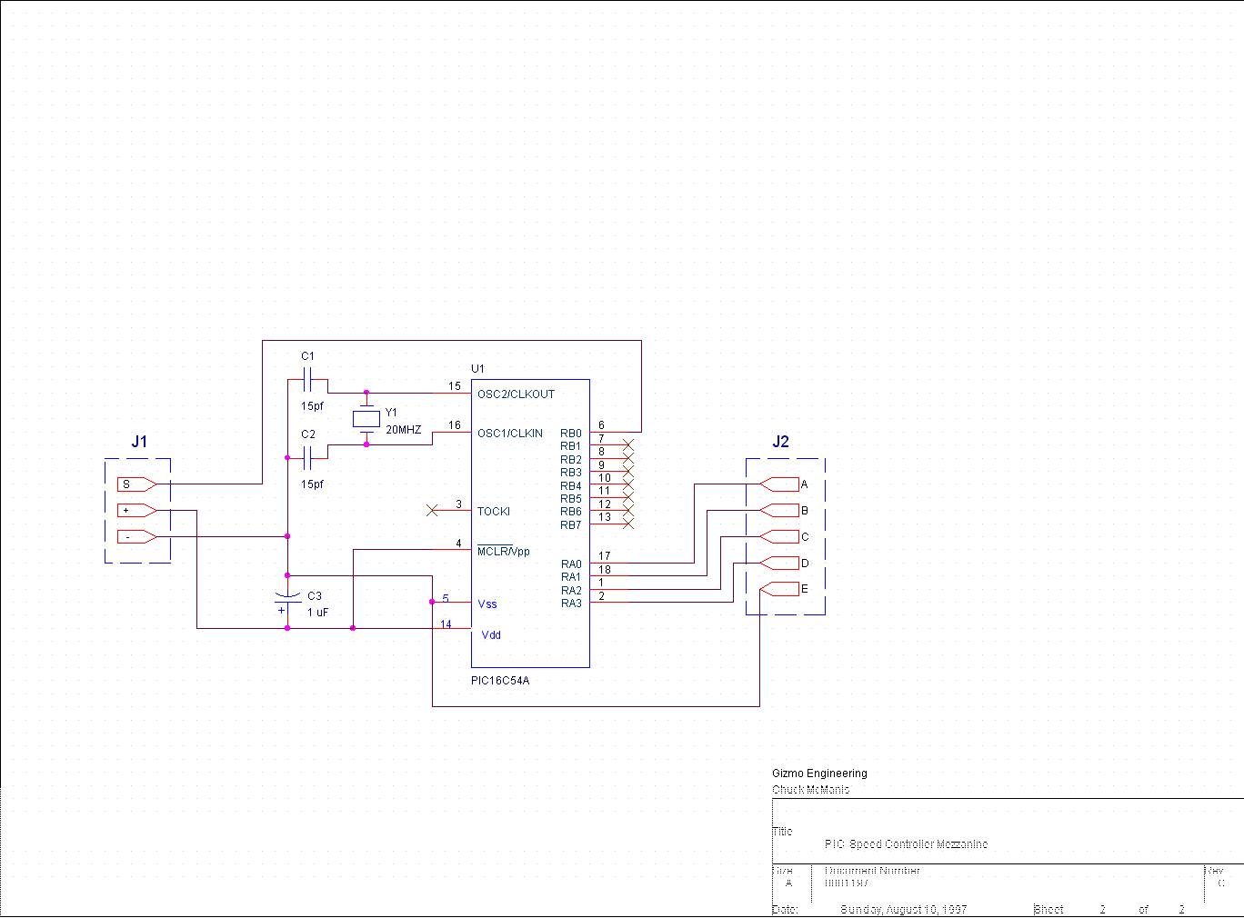 I built that bridge but with IRF540 FETs; Im not driving massive motors with it. Seems fine so far tho. I suspect if you just scale up the FETs you may run into some problems with voltage spikes, you might need snubber diodes. If you heatsink the FETS you should get 10A out of it. Is the motor you're using rated at 10A stall current or running current? Id test first cos a 10A motor may pull 50A stalled = smoked FETs. There are probably better circuits out there; I prefer to use just N FETs rather than both. |
|
|
|
|
Logged
|
Experimentum solum certificat in talibus.
Experiment is the only safe guide
|
|
|
dex
Newbie
Offline
Posts: 10
Thank You
-Given: 12
-Receive: 0
|
|
« Reply #10 on: December 08, 2007, 03:47:10 03:47 » |
|
The motor I'm trying to drive runs a small positive displacement pump, which is used to pump melted candle wax. I'm trying to help a friend that has a candle business. He has to fill hundreds of small glass containers with wax and I'm trying to improve his productivity by using a PIC to drive the pump based upon an adjustable timer (he needs continuous and timed modes). He also needs to be able to run the pump in reverse in case of overfills.
Iâll see if I can measure the lock rotor amps on the motor but it may be difficult.
|
|
|
|
|
Logged
|
|
|
|
truebit
Newbie
Offline
Posts: 7
Thank You
-Given: 4
-Receive: 1
|
|
« Reply #11 on: December 11, 2007, 11:49:47 23:49 » |
|
Hi,
I have built a PIC driven MOSFET "H" bridge using IRFP260N devices driven with HP HCNW3120 opto isolated mosfet drivers. This arrangement has a number of advantages.
1, If the opto diodes are wired "back to back" on each side it is not possible for both top and bottom devices to be ON at the same time.
2, The drivers have a longer turn on time than off, this helps to ensure a smooth transition.
3, There is no practical limit to the high side voltage (up to 1500v is OK)
4, If you arrange the software to not allow the PWM duty cycle to exceed about 90% the top driver power supply only requires a high speed diode (boot strap).
5, The isolation helps keep the nasty high voltage high speed noise out of the PIC.
I have been using a number of these at 150V and 10A in a PID based servo CNC drive with no problems.
|
|
|
|
|
Logged
|
|
|
|
belinao
Newbie
Offline
Posts: 16
Thank You
-Given: 1
-Receive: 12
|
|
« Reply #12 on: December 12, 2007, 01:11:06 13:11 » |
|
i would try using a pnp bipolar for the upper mosfet and a simple npn for the bottom, it is cheaper....
have you tried that? i could send u the circuit if u want...
|
|
|
|
|
Logged
|
|
|
|
rinderpest
Junior Member
Offline
Posts: 41
Thank You
-Given: 23
-Receive: 11
All machines are amplifiers
|
|
« Reply #13 on: December 12, 2007, 05:47:12 17:47 » |
|
@dex If you just need an on / off control with occaisional reverse you can get away without the complication of a bridge. Microchip have a nice app note with code and circuit here: http://ww1.microchip.com/downloads/en/AppNotes/00847a.pdfIt has braking and although it is one way it only uses one FET. You can use a relay for reversing since you wont reverse that often (I imagine) it wont kill the relay. You should search epanorama etc for radio control ESC circuits, there are some good solutions out there; well documented too. I've just changed PC otherwise Id spam you with links. here is link for the isolated bridge below: http://www.mcmanis.com/chuck/robotics/projects/h-bridge/h-bridge.htmltruebit's sounds perfect, just pricier... Im a bit of a pauper so my solutions to things are usually just good enough, Id do a better job if I could afford it! |
|
|
|
|
Logged
|
Experimentum solum certificat in talibus.
Experiment is the only safe guide
|
|
|
truebit
Newbie
Offline
Posts: 7
Thank You
-Given: 4
-Receive: 1
|
|
« Reply #14 on: December 13, 2007, 02:29:50 14:29 » |
|
truebit's sounds perfect, just pricier...
Im a bit of a pauper so my solutions to things are usually just good enough, Id do a better job if I could afford it! From memory the HCN3150 (0.5A drive version) are only about $1.50 ea in small quantities and all the other components you would need anyway, so this is not very expensive (unless you are building a large number). Regards.. |
|
|
|
|
Logged
|
|
|
|
rinderpest
Junior Member
Offline
Posts: 41
Thank You
-Given: 23
-Receive: 11
All machines are amplifiers
|
|
« Reply #15 on: December 13, 2007, 04:31:18 16:31 » |
|
Nice, thanks for the tip. I've just ordered some for some other stuff Im doing.
In terms of pricier I was thinking of servo drives rather than steppers.
Good tip re hardware shoot-through avoidance with opto wiring. I use a 7400 in mine, I smoked an earlier bridge by losing my presence of mind when debugging. Red face and burned fingers...
I've driven small motors straight off Microchips TC4427 MOSFET drivers, they're good for several amps.
Did you code the PID loop yourself? Im intending to tackle that but my maths isnt fantastic so Id need isolation & books for weeks to get anywere.
Im making a PCB router out of old printer/scanner tat, looking at one of those cheap chinese micromills. Think there is a yahoogroup on CNC conversion for them, pluys plenty sites.
@belinao Transistors are good for small motors but they have a fairly high on resistance so you burn power that way, plus the voltage drop. If you mix N and P channel FETs in a bridge you lose power too because the P FETs have a higher on resistance compared to N type.
|
|
|
|
« Last Edit: December 13, 2007, 04:41:42 16:41 by rinderpest »
|
Logged
|
Experimentum solum certificat in talibus.
Experiment is the only safe guide
|
|
|
dex
Newbie
Offline
Posts: 10
Thank You
-Given: 12
-Receive: 0
|
|
« Reply #16 on: December 13, 2007, 06:37:04 18:37 » |
|
rinderpest, thanks I'll do a little web searching for radio controlled ESC's. Your idea of using a relay may be the ticket. I'll have to pass that idea past my friend, since he will be the end user of the circuit. I imagine he will still want some sort of speed control. The candles he pours vary quite a bit in size so whatever the design it needs to be flexible.
By the way systems like what I'm trying to put together are selling for $1,000+ that is a very high markup when you look at the component costs.
|
|
|
|
|
Logged
|
|
|
|
rinderpest
Junior Member
Offline
Posts: 41
Thank You
-Given: 23
-Receive: 11
All machines are amplifiers
|
|
« Reply #17 on: December 13, 2007, 10:58:03 22:58 » |
|
Hers an crap circuit (its pulse frequency modulation not PWM) that shows the rough idea of the FET and relay idea for occaisional reverse. 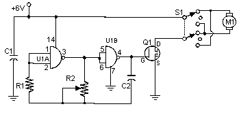 If you ignore the oscillator made from NAND gates and drive the FET with a PWM waveform from your PIC you will have speed control. Wire a relay in place of the switch and use a small transistor to drive the coil with another PIC output. This only uses 2 lines so you've loads left for sensors, RS232, LCD etc. |
|
|
|
|
Logged
|
Experimentum solum certificat in talibus.
Experiment is the only safe guide
|
|
|
|
microtest
Guest
|
|
« Reply #18 on: December 17, 2007, 11:04:34 23:04 » |
|
you can put a 7407 and 1k R to Vcc like 12 volts to drive a irfp450 and a 3 in Insulation Power Supplies
|
|
|
|
|
Logged
|
|
|
|
|


