Sonsivri
 
*
Welcome, Guest. Please login or register.
Did you miss your activation email?
March 19, 2024, 08:44:15 08:44


Login with username, password and session length


Pages: [1]
Print
Author Topic: Electronic Display Board with 4" inches  (Read 3421 times)
0 Members and 1 Guest are viewing this topic.
goslock
Newbie
*
Offline Offline

Posts: 13

Thank You
-Given: 12
-Receive: 7


« on: April 02, 2008, 01:14:30 01:14 »

Well I have just finished a project that I ordered for an electronic board, which will serve for the indication of tank mixing and production lines in a company here in my country, the project fairly economical with regard to buy the board already done.

The board has two base stations for entering changes which is at the second level of the plant and the remote station which is at a distance of approximately 20 meters which is located on the first level. The operator can send two changes at the same time (tank - line). The communication between the two bases is serial cable with a length of 25 metres each station has the following features:

Base Station
       * 2 x 20 LCD display for the data entered
       * Keyboard 4 x 4 matrix for entry operator
       * PIC16F877 and brain.
     
Remote Station
       * 2 x 20 LCD display for the data entered
       * Keyboard 4 x 4 matrix for entry operator
       * PIC16F877 and brain.
       * Siren for the indication has been received that a change
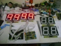
       * 8 display 7 segments 4"

Hen I planted the project, the question menera making each separate part of the plate pic and the party power to the union used straps with IDC connectors 20 and 10 pin terminals besides 2 to coneciones supply and alarm.

The operation is simple operator to enter any changes must enter a 4-digit password which can be changed without any clear poblema before entering the key today. Good entering the key, then asks you to enter the number of tank (2 digits) and then the number of line (2 digits), then shows you to confirm or reject the changes. If these are sent remote station receives them and trigger the siren for a time of 25 seconds or turns off if the operator enters its key at the remote station to watch the change received this key also is 4 digits. The operator can make mistakes just 3 times if you enter the wrong password, but the station remotely send an error to the base station and this will have to re-enter the change until they receive from the operator correctly. Well more or less works well leave them some pictures and some videos of the board. Greetings to all and good luck


Here video

Video 1
Video 2

At the moment I am working on a clock
    * DS1307
    * 16F88
    * 4 Dispaly  4" inch
    * LM35 (Temperature meter)
« Last Edit: April 02, 2008, 01:19:36 01:19 by goslock » Logged
smainj
Active Member
***
Offline Offline

Posts: 125

Thank You
-Given: 70
-Receive: 75


WWW
« Reply #1 on: April 04, 2008, 10:24:41 10:24 »

no code no schema
what is the utility of this topic

 Huh Huh
Logged

sohel
Senior Member
****
Offline Offline

Posts: 442

Thank You
-Given: 166
-Receive: 149


« Reply #2 on: April 04, 2008, 07:22:09 19:22 »

he want to introduce himself. or advertisement Grin
Logged
goslock
Newbie
*
Offline Offline

Posts: 13

Thank You
-Given: 12
-Receive: 7


« Reply #3 on: April 06, 2008, 01:03:38 01:03 »

First presentation  Grin Grin, if someone is interested to ask

Logged
pouchito
Newbie
*
Offline Offline

Posts: 29

Thank You
-Given: 61
-Receive: 2


« Reply #4 on: April 06, 2008, 11:22:46 11:22 »

nice project dude:)
thanks for sharing Cheesy but pls can you provide the code or the hex so we will be able to test it ?
Logged
smainj
Active Member
***
Offline Offline

Posts: 125

Thank You
-Given: 70
-Receive: 75


WWW
« Reply #5 on: April 06, 2008, 06:39:58 18:39 »

yes nice project but the display system is not very good
why you don't have used like this schema

it is more easy to build and low cost
Logged

goslock
Newbie
*
Offline Offline

Posts: 13

Thank You
-Given: 12
-Receive: 7


« Reply #6 on: April 08, 2008, 04:40:27 04:40 »

yes nice project but the display system is not very good
why you don't have used like this schema
it is more easy to build and low cost

You have reason in the diagram is easier multiplexed, but I forgot to add that in the second diagram, just what use to simulate as it does not include ahi the power part because the display work from 7 to 9 volts and try to use multiplexacion but had some problems with the sampling keyboard as input data, why use the records and then hand power to ULN2803. That was the reason.
« Last Edit: April 08, 2008, 05:29:25 05:29 by goslock » Logged
krumper88
Newbie
*
Offline Offline

Posts: 15

Thank You
-Given: 133
-Receive: 1


« Reply #7 on: April 11, 2008, 08:04:23 20:04 »

Where did you get the 4" displays?
Logged
Pages: [1]
Print
Jump to:  


DISCLAIMER
WE DONT HOST ANY ILLEGAL FILES ON THE SERVER
USE CONTACT US TO REPORT ILLEGAL FILES
ADMINISTRATORS CANNOT BE HELD RESPONSIBLE FOR USERS POSTS AND LINKS

... Copyright © 2003-2999 Sonsivri.to ...
Powered by SMF 1.1.18 | SMF © 2006-2009, Simple Machines LLC | HarzeM Dilber MC