biomed12
Junior Member

 Offline Offline
Posts: 94
Thank You
-Given: 67
-Receive: 5
|
 |
« on: November 10, 2016, 09:25:23 21:25 » |
|
Hello,
I will use an instrumentation amplifier using a dc 9v power supply. So, I need to apply a negative voltage to opamp. I will use a clasical voltage divider to obtain negative difference. There is no problem until here. But, Does the middle of the voltage divider be my reference for all circuit? For example, can I apply this reference to the PIC gnd without any problem and my VCC is upper side of voltage divider? More clear, do MCUs runs according to voltage difference or according to a real 0V reference?
EDIT:
I attached a image from PIC datasheet.
|
|
|
|
« Last Edit: November 10, 2016, 09:52:08 21:52 by biomed12 »
|
 Logged
|
|
|
|
optikon
Cracking Team
Hero Member
Offline
Posts: 858
Thank You
-Given: 1128
-Receive: 2007
|
 |
« Reply #1 on: November 10, 2016, 10:12:20 22:12 » |
|
Hello,
I will use an instrumentation amplifier using a dc 9v power supply. So, I need to apply a negative voltage to opamp. I will use a clasical voltage divider to obtain negative difference. There is no problem until here. But, Does the middle of the voltage divider be my reference for all circuit? For example, can I apply this reference to the PIC gnd without any problem and my VCC is upper side of voltage divider? More clear, do MCUs runs according to voltage difference or according to a real 0V reference?
EDIT:
I attached a image from PIC datasheet.
your question seems posed a little odd. can you show us your proposed circuit? MCU- run it from VDD (say 3 or 5V) with respect to ground. Opamp, you can use +9V and its not clear how you think you can make -9V. In any case, you cannot allow any voltage more negative than -0.3V to get to MCU pin. I wouldnt let anything past VDD on the positive side get there either unless the PIC has an input that can tolerate it. Or are you talking about making a floating supply somehow? You can take away alot of our guessing by drawing us your complete idea with all the supplies and voltage dividers shown. |
|
|
|
|
Logged
|
I can explain this to you. I can't comprehend it for you.
|
|
|
Vineyards
Active Member
Offline
Posts: 170
Thank You
-Given: 66
-Receive: 37
|
|
« Reply #2 on: November 10, 2016, 10:20:18 22:20 » |
|
You could use a three pin virtual ground generator e.g. TLE2426. Using resistors for rudimentary solutions would work but you will certainly need some current to flow through your opamp and that is when problems begin to arise. When the current capacity is exceeded, there will be a lot of noise caused by clips. The above ic is very easy to use and will source or sink 20mA which is enough for most opamps. The noise problem will disappear and you will also get voltage regulation. Check it out. I used it quite a few times including in serious commercial projects and they performed great.
|
|
|
|
« Last Edit: November 19, 2016, 02:47:18 14:47 by Vineyards »
|
Logged
|
|
|
|
biomed12
Junior Member
Offline
Posts: 94
Thank You
-Given: 67
-Receive: 5
|
|
« Reply #3 on: November 10, 2016, 10:59:39 22:59 » |
|
Ok, clearly, I attached what I want to do. Input signal of opamp is -+5mV sensor output.
EDIT: 5. pin is connected to the GND pin terminal.
|
|
|
|
« Last Edit: November 10, 2016, 11:02:33 23:02 by biomed12 »
|
Logged
|
|
|
|
optikon
Cracking Team
Hero Member
Offline
Posts: 858
Thank You
-Given: 1128
-Receive: 2007
|
|
« Reply #4 on: November 11, 2016, 02:10:29 02:10 » |
|
You should buffer the GND signal for low impedance reference. How much current will you have flowing in your split resistive ground? We dont know about all your I/O on the MCU. And your R2 will interact with your reference resistors in your instrument amp if you don't buffer it.
You have a ~ 5mV signal you are presumably going to measure with an A/D ? You'd better make a good low noise ground reference in your system if you want good measurement performance.
|
|
|
|
« Last Edit: November 11, 2016, 02:16:56 02:16 by optikon »
|
Logged
|
I can explain this to you. I can't comprehend it for you.
|
|
|
vern
V.I.P
Active Member
 Offline
Posts: 147
Thank You
-Given: 7
-Receive: 42
|
|
« Reply #5 on: November 11, 2016, 09:10:34 09:10 » |
|
biomed 12, your circuit will not work. You have to bypass your voltage divider R1/R2 with two caps, 100nF at least. Or better yet: use a chip like TLE2426 to create a virtual GND. You should also not operate your PIC with its GND tied to the virtual GND, because the PIC's supply current would run through R2 in your schematic, no good to have digital currents running through an analog ciruit. The PIC should have GND on DC V-, the INA is connected on V+ / V- and the the virtual GND is for INA signal reference only! The PIC does not have diffential AD Converter inputs, so the INA output has to be referenced to the PIC GND, in your case V-. This can be done with a resistor voltage divider, which has the disadvantage of attenuating your signal, so you should go with a non-inverting summing amplifier, like this example http://electronics.stackexchange.com/questions/37095/level-shifting-a-2-5v-signal-to-0-5v. If you only need AC signals fed to the PIC, you can use a decoupling cap to have the signal referenced to the PIC input. But in that case you would not need an instrumentation amplifier anyway, any Op-amp would do, which could be run from a single voltage supply. |
|
|
|
|
Logged
|
|
|
|
Sideshow Bob
Cracking Team
Hero Member
Offline
Posts: 1012
Thank You
-Given: 235
-Receive: 994
|
|
« Reply #6 on: November 11, 2016, 10:28:47 10:28 » |
|
First is it any reason why you not can have split supply? Second I do not know if you know the book The Art of Electronics by Horowitz and Hill. Your circuit would have easy earned a place among thier Bad Circuits ideas. You may take a look at this site as a crash course https://tangentsoft.net/elec/vgrounds.html As you may know or probably not know is that a split power supply can created using two DC power supplies or batteries for that matter, like shown here 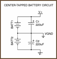 As others also have mentioned is that the output from the INA114 will be bipolar. But the ADC on your DSPIC is unipolar only. This is something you have to tackle in your design. I really hope your project not is due in the end december. Because We've got a long way to go (and a short time to get there) |
|
|
|
|
Logged
|
I have come here to chew bubblegum and kick ass... and I'm all out of bubblegum
|
|
|
biomed12
Junior Member
Offline
Posts: 94
Thank You
-Given: 67
-Receive: 5
|
|
« Reply #7 on: November 11, 2016, 12:12:06 12:12 » |
|
You should buffer the GND signal for low impedance reference. How much current will you have flowing in your split resistive ground? We dont know about all your I/O on the MCU. And your R2 will interact with your reference resistors in your instrument amp if you don't buffer it.
You have a ~ 5mV signal you are presumably going to measure with an A/D ? You'd better make a good low noise ground reference in your system if you want good measurement performance.
Clearly, there are not much current consumption, i think maximum of it is about 70 mA. Many of IO are empty. Just SPI module and AD module will be used. Posted on: November 11, 2016, 12:58:45 12:58 - Automerged
First is it any reason why you not can have split supply? Second I do not know if you know the book The Art of Electronics by Horowitz and Hill. Your circuit would have easy earned a place among thier Bad Circuits ideas. You may take a look at this site as a crash course https://tangentsoft.net/elec/vgrounds.html As you may know or probably not know is that a split power supply can created using two DC power supplies or batteries for that matter, like shown here As others also have mentioned is that the output from the INA114 will be bipolar. But the ADC on your DSPIC is unipolar only. This is something you have to tackle in your design. I really hope your project not is due in the end december. Because We've got a long way to go (and a short time to get there) SSBoby, The prototype is running like this now with two 9V batteries. But now, I should use a DC power supply to make the pcb more clear and nice. So, I dont want to use an additional battery. I hope, I will finish the project in next 2 weeks and I will share on sonsivri. There are just 2 issue left. First is this, second is another that is related to cables. I learned much practical knowledge. Posted on: November 11, 2016, 01:07:06 13:07 - Automerged
Why do you need a negative voltage for the INA ? You can use a positive voltage and connect V- of INA to GND of the microprocessor.
After that you have the choice to connect Vref pin of INA to GND or to another voltage (for example V-/2) in order to introduce some offset in the output of the INA. In this latter case it is better to use a shunt regulator or a reference to obtain a stable and noiseless 0 voltage output.
Because, the input signal has some negative components according to 0V. The measurement is bipolar also. As you know, if there is no negative supply for INA, negative components of signal will be cutted. |
|
|
|
|
Logged
|
|
|
|
Sideshow Bob
Cracking Team
Hero Member
Offline
Posts: 1012
Thank You
-Given: 235
-Receive: 994
|
|
« Reply #8 on: November 11, 2016, 12:39:38 12:39 » |
|
You should concentrate all your efforts in getting this thing to work. Do not think about making things nice. It will only mess up your design if a thing is not broken dont fix it. You should also keep the batteries. In your report you can argue that that batteries are best to use from a medical safety aspect. It is a truly valid argument. As a bonus, using batteries will also help you to avoid noise problems that some sort mains of powered power supply probably will give you.
Ps! You do know that using the method suggested in post 3 you will not get +/- 9 volt but +/- 4.5 volt
|
|
|
|
|
Logged
|
I have come here to chew bubblegum and kick ass... and I'm all out of bubblegum
|
|
|
biomed12
Junior Member
Offline
Posts: 94
Thank You
-Given: 67
-Receive: 5
|
|
« Reply #9 on: November 11, 2016, 01:51:12 13:51 » |
|
You should concentrate all your efforts in getting this thing to work. Do not think about making things nice. It will only mess up your design if a thing is not broken dont fix it. You should also keep the batteries. In your report you can argue that that batteries are best to use from a medical safety aspect. It is a truly valid argument. As a bonus, using batteries will also help you to avoid noise problems that some sort mains of powered power supply probably will give you.
Ps! You do know that using the method suggested in post 3 you will not get +/- 9 volt but +/- 4.5 volt
Boby, You are definetely right, batteries are the cleanest sources for medical instrumentation. But due to your comment, I asked myself, how companies do this without using batteries? Now, I realized that I hate analog electronics. lol. Digital design is more friendly to me. Just And, Or, Not gates. so, code it. EDIT: you was right. I asked one of our electonics department professors, he said me that "design a power supply that is your own". So, I will use a battery for now, maybe i will design later a new power supply. Thanks. |
|
|
|
« Last Edit: November 11, 2016, 03:58:47 15:58 by biomed12 »
|
Logged
|
|
|
|
jzaghal
Active Member
Offline
Posts: 165
Thank You
-Given: 502
-Receive: 55
|
|
« Reply #10 on: November 11, 2016, 03:45:34 15:45 » |
|
|
|
|
|
|
Logged
|
|
|
|
Signal
Active Member
Offline
Posts: 200
Thank You
-Given: 113
-Receive: 81
|
|
« Reply #11 on: November 11, 2016, 06:15:37 18:15 » |
|
I will use an instrumentation amplifier using a dc 9v power supply. So, I need to apply a negative voltage to opamp.
I do not see why you need 9V for power supply. And I do not see why you need negative voltage for opamp (even for chosen INA114). You need to use external 9V supply not to divide it but as input for voltage regulator. Output 5V is OK for both dsPIC30 and INA114. Virtual ground as fellows suggested earlier (by using TLE2426 for example or simple R-RC divider) is not for powering PIC - it is for signal reference. Check its frequency response and noise. Virtual ground potential has to have strong connection to reference of your ADC. In case of TLE2426 I'd say pins IN and COMMON should be connected to VREF+ and VREF- of your ADC. But the key question - connection of sensor. There are cases when you need a true negative rail (that is not the "minus" terminal of your 9V supply that has to be ground). In that cases for supplying one amplifier IC the mainstream solution is to use charge pump. Several times I used TPS60403 (switched capacitor charge pump). Couple of times I used charge pump voltage doubler (Greinacher circuit) drived by PWM output of controller (though this is slightly out of specified pin drive capability of uC for starting charge period). Last variant with two phases gives extremely low ripples. |
|
|
|
|
Logged
|
Give a right name to a right game and play it right
|
|
|
PICker
Active Member
Offline
Posts: 162
Thank You
-Given: 208
-Receive: 110
|
|
« Reply #12 on: November 11, 2016, 09:54:43 21:54 » |
|
In some low-current single-supply applications it could be sufficient to generate a middle point voltage (i.e 2.5V in you are working with a Vcc of 5V) with a LDO voltage reference used as "virtual ground". Usually this is a standard approch where a negative power supply is difficult to obtain (battery operated circuits).
You ca try to re design your circuit for single supply operation (if possible).
You can start to have a look at: ww1.microchip.com/downloads/en/AppNotes/00682D.pdf
If you need to extend the voltage span under the ground, the circuits suggested form the other members of the forum are OK.
|
|
|
|
|
Logged
|
|
|
|
Gallymimu
Hero Member
Offline
Posts: 704
Thank You
-Given: 152
-Receive: 214
|
|
« Reply #13 on: November 12, 2016, 10:16:45 22:16 » |
|
These days the easiest solution is a single chip inverting charge pump. You can get 100mA and even 200mA out of them TI, and LT make some good easy to use ones.
Otherwise little isolated DC to DC converter modules are nice no-brainers as well to generate negative voltages. You can also pretty easily get 5V in to +/-5V out isolated or non-isolated modules for one off projects like this they work great.
Don't feel bad about suggesting a resistive divider for your first power supply. It's probably the most common junior suggestion/mistake I see with interns and people who are learning EE.
|
|
|
|
|
Logged
|
|
|
|
biomed12
Junior Member
Offline
Posts: 94
Thank You
-Given: 67
-Receive: 5
|
|
« Reply #14 on: November 13, 2016, 12:15:58 00:15 » |
|
These days the easiest solution is a single chip inverting charge pump. You can get 100mA and even 200mA out of them TI, and LT make some good easy to use ones.
Otherwise little isolated DC to DC converter modules are nice no-brainers as well to generate negative voltages. You can also pretty easily get 5V in to +/-5V out isolated or non-isolated modules for one off projects like this they work great.
Don't feel bad about suggesting a resistive divider for your first power supply. It's probably the most common junior suggestion/mistake I see with interns and people who are learning EE.
Dear Gallymimu, This is definetely what I want to. I am attaching an SS to show it precisely. In addition, I was looking for some reverse polarity adapters. I said the SSBoby member "I would use a battery" but as you know, problems are always make confused engineers brain(I am not enginner yet:|). So, I thougt, the low cost solution. https://www.aliexpress.com/item/1PCS-High-quality-AC-DC-9V-1A-Switching-Power-Supply-adapter-Reverse-Polarity-Negative-Inside-EU/32491101551.html?spm=2114.13010208.99999999.271.TE336RI thougt to regulate the two negative and positive input to enter to all of the circuit. But now, I will buy a new ltc1261 from DigiKey and have fun. I hope, I understand everything rightly. Thanks, 1000 times. Edit: oops, I didn't care about 10ma output. Anyway, I will look others. Edit2: It looks like 10mA output is enough for INA114. An image was added from its datasheet. |
|
|
|
« Last Edit: November 13, 2016, 12:44:31 00:44 by biomed12 »
|
Logged
|
|
|
|
Gallymimu
Hero Member
Offline
Posts: 704
Thank You
-Given: 152
-Receive: 214
|
|
« Reply #15 on: November 13, 2016, 04:58:10 04:58 » |
|
This is a nice easy to use one as well with more current: http://www.linear.com/product/LTC1983, but the 1261 should also be fine. |
|
|
|
|
Logged
|
|
|
|
solutions
Hero Member
Offline
Posts: 1826
Thank You
-Given: 656
-Receive: 905
|
|
« Reply #16 on: November 19, 2016, 02:01:44 14:01 » |
|
Among other problems you are likely to encounter with your approach, you need a LPF between the op amp and the dsPIC...
|
|
|
|
|
Logged
|
|
|
|
|


