Sonsivri
 
*
Welcome, Guest. Please login or register.
Did you miss your activation email?
April 19, 2024, 03:49:55 15:49


Login with username, password and session length


Pages: [1]
Print
Author Topic: Clean Sinewave from Microcontroller (for Morse keyer sidetone)  (Read 4389 times)
0 Members and 1 Guest are viewing this topic.
Signal
Active Member
***
Offline Offline

Posts: 197

Thank You
-Given: 111
-Receive: 81


« on: September 04, 2014, 01:53:22 01:53 »

The project began 3 years ago. In the beginning it was a complex mess of desires. I wanted to make with my kids something with a material result, to share with them some flavors of my profession, to acquaint them with things that they will never meet after or maybe fascinate. I did not intend practical value of final product but operational capability had to be undoubtful.

Eventually I realize that it will be fun to make (yet another) electronic Morse keyer. In the absence of transceiver it would be just a toy that could be used for (improbable) education. For two involved pupils headset seems to me not the best choice - loudspeaker won. I did not want to stuck with precise mechanics so decided to make capacitive paddle. Stand-alone usage is a benefit that is worth its price of battery changing. Programming as a part of work was meant completely essential, thus controller took it's place in plan. Finally I expect to see the monoblock with battery supply, low power loudspeaker, capacitive paddle for iambic mode and mechanic knobs for tuning.

Also I wanted to use parts on hand not from store as much as possible and to use discrete components instead of integral ones where it is still fun. That style was presumed to be more illustrative for education and more appropriate to amateur spirit. Thus controller was chosen from remainders at work, inductor was wound on toroidal core from old motherboard, potentiometers were from tonestack of old Blaupunkt and audio amplifier was made of five sot-23 transistors. Only loudspeaker was ordered at web-store to keep things smaller. I made schematics and PCB layout, together with children we made PCB using laser printer and FeCl3. Kids made solder works and algorithm while I coded this algorithm and its iterations until working device. This part of work was completed relatively fast for 3 weekends. After first successful tests the PCB was packed on the shelf and only recently 3 years later I have made enclosure to show to grown children how projects must be finished actually ;)

To make project more interesting for me I complicated the task. The sidetone must be
   a) as clean as possible,
   b) without edge clicks (claps) and
   c) pitch must be tunable.

I saw several ways to achieve this:
   1) functional generator: uC + DAC + antialiasing filter
   2) functional generator: uC + R-2R ladder + antialiasing filter
   3) functional envelop generator + tunable sine-wave oscillator + multiplier/modulator
   4) tunable square-wave generator + fixed filter
   5) tunable square-wave generator + tunable bandpass filter

First way is too serious for given project. Second was checked but simulated sound quality was not enough for me – quantization noise was too strong, far from clarity I expected. Fixed filter approach is good in case of narrow range of tuning. But if we wider it to nearly octave a filter becomes too complex and even more important edges become audible due to wider pass band of filter.

Tunable sine-wave oscillator itself is not as simple as desired for current application and edges still  require additional handling. I found one fixed pitch variant made by Jason Mildrum (NT7S) http://nt7s.com/2008/11/nt7s-code-practice-oscillator/. Tom Dean (K7TPD) replicated it with some modifications http://k7tpd.yolasite.com/ and provides a sample of sound http://youtu.be/AKaA33ozrPw. Still audible edges (masked by clicks of mechanics) but of course incomparably better than square-wave.

Functional envelop generator solves the problem with edge claps but does nothing with purity of sinewave that requires separate components. G. Forrest Cook already passed that way: http://www.solorb.com/elect/hamcirc/sidetone/

Consequently I was fascinated to solve the problem by PWM based generator and tunable bandpass filter. For reasons of aesthetics (better say mimimalism) the filter must be active with one active element – transistor, and be controlled digitally.

I reflected for a moment over switched capacitor filter (example http://newenglandqrp.org/nescaf, though my personal choice would be LTC1059) but there were no magic for me at the time, besides footprint and budget would be considerably bigger, and requirements for supply voltage would be more constrained – the same factors as for more flexible DAC/DSP solution.

So here is the block diagram:

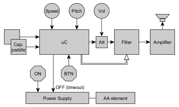
(functional_diagram.png)

Volume control potentiometer is placed before filter because I wanted to eliminate redundant buffer cascade between filter and amplifier –  load to filter has influence on its characteristics. Besides the PCB topology became more balanced. Controlling of volume by PWM settings is not a good idea since filter is not perfect and it is better to minimize amount of harmonics of  initial signal.

The first guess (with success) how to control filter was to change pull-down resistance by open drain outputs of controller. As the base for the filter I took one with a phase shift feedback circuit similar to phase shift oscillator. Actually I found widely replicated circuit used in colour organ and made some modifications. I can not find the origin to reference it here. Instead – some links to “followers” (just pictures, because all sites are not in English):
http://mozgochiny.ru/wp-content/uploads98983jkhdkjf9873/2011/11/6f43866656.png
http://umup.ru/sites/default/files/images/122_1.JPG
http://pro-radio.ru/user/uploads/212680.jpg

Fortunately there is an area in multidimensional space of resistors values where adjustment of one pull-down impedance causes central frequency to run through octave with gain difference about 3 dB and with suitable bandwidth.

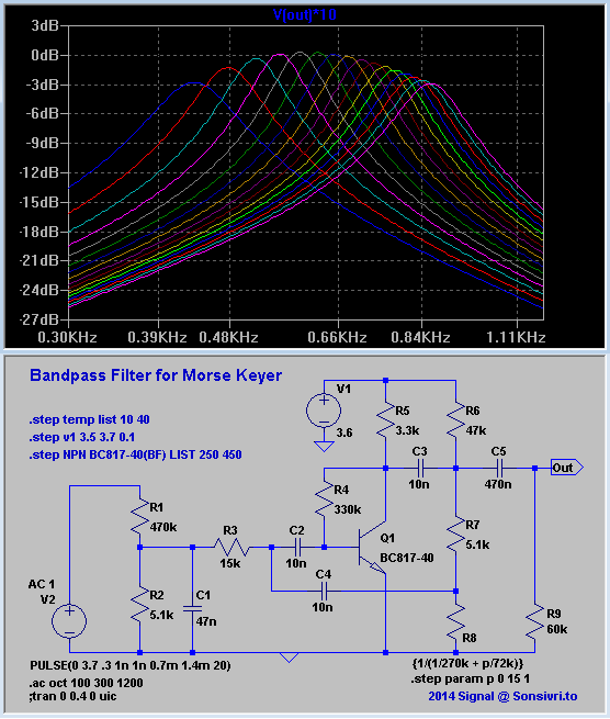
(phase_shift_filter.png)

R1R2 divider keeps level of signal low enough for lower non-linear distortions and eliminates influence of Volume control potentiometer on impedance R2|C1 and consequently on filter characteristics. R8 is a combination of binary weighted admittances connected to ground by uC port pins. Here four OD pins are used. R6 was added for positive offset on uC pins. R9 is an equivalent of input resistance of next cascade. C1 slightly improves suppression of high harmonics and (nice to think) protects low level input from noise. Temperature stability is quite good, while dependance on transistor gain is significant. Darlington solves this problem completely, but for single unit production calibration is anyway needed, so minimalism won.

Although an amplifier could be integral in little SOIC-8 package I decided to make it with discrete transistors for earlier mentioned reasons.
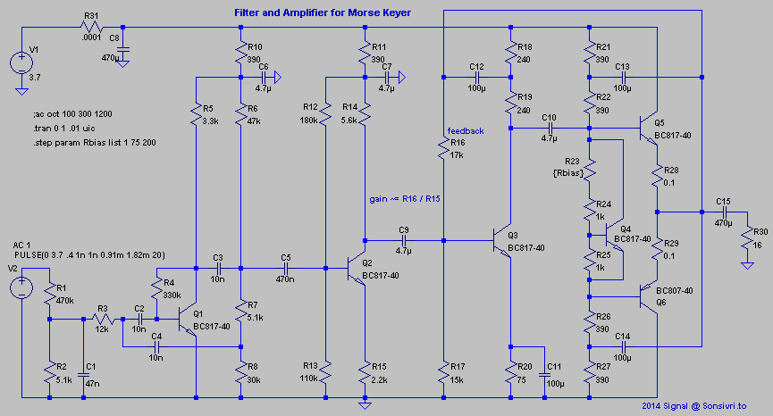
(filt_amp.png)

AB-class amplifier works on a 16 Ohm load through coupling capacitor. For better power efficiency to increase output swing the bootstrapping is used: C12,C13,C14. Q4 makes bias for Q5Q6 voltage follower stage. C11 and a feedback R16 makes input impedance of Q3 stage very low (Q3 base is virtually a fixed point) so current amplifier/buffer Q2 stage works as voltage to current converter. Gain from Q2 to R30 is mainly defined by R16/R15 ratio similar to inverting op-amp circuit.

R28, R29 were expected to be redundant here but were placed to test actual influence. Finally 0.1 Ohm resistors were placed just for fun – dissipated power is so low that idle current is stable even with zero Ohm.

Increasing R23 will lower nonlinear distortions but in practice with chosen loudspeaker and actual quality of filtration I can not hear any difference so zero Ohm value is used to lower power consumption.

Simulated and captured waves look pretty similar:

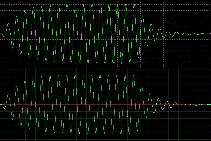
(simulated_vs_captured.png)

To get subjective impression the wav-file is attached. There are several portions of pure sine-wave modulated at zero-crossings by square envelop (marked by =) and signal captured from output of represented device (marked by ~) :  { =F  ~F  ~F~  =M  ~M  ~m  ~o }. “~F~” is a copy of  “~F” that was filtered in audio editor by the similar 2-order bandpass filter (~130 Hz @ 3 dB). Recordings was made with unattached load – only last “o” with attached 16 Ohm loudspeaker. Last portion of recording was made with volume set to the half that slightly lower even harmonics that is indistinguishable by ear.
Measured level of harmonics (volume at max, w/o load, fundamental tone 0 dB):
   -44, -34, -71, -42, -61, -53, -70, -53, -68, -62, -76, -62, -76, -68, -92, -68 (dB).

Zip-file also contains LTspice schematic asc-files that correspond to given snapshots.

Purity of the derived sine-wave is not perfect but could be acceptable – for fast speeds edges mainly mask weak harmonics. Still not perfect edges – slightly audible claps. Narrowing pass band or better use two filters in sequence solve this problem, but who need it? I, personally, consider quality as acceptable, approach as efficient and experiment as successful. Enjoy.
« Last Edit: September 04, 2014, 09:57:59 21:57 by Signal » Logged

Give a right name to a right game and play it right
DreamCat
Senior Member
****
Offline Offline

Posts: 284

Thank You
-Given: 223
-Receive: 116


« Reply #1 on: September 08, 2014, 11:22:56 11:22 »

why not use op-amp to design the filter and amplifier circuit?
Logged

May be I expressed the wrong meaning, sorry for my bad english. Please correct it for me if you can.
an007_rld
Junior Member
**
Offline Offline

Posts: 52

Thank You
-Given: 33
-Receive: 52


« Reply #2 on: September 08, 2014, 01:07:20 13:07 »

You can also use:
1. A switching capacitor filter and a controller: http://www.maximintegrated.com/en/app-notes/index.mvp/id/2081
2. Magic Sinewave (a cool technique to minimize harmonics): here http://www.tinaja.com/magsn01.shtml and here http://www.sxlist.com/techref/io/pwm/harmonic.htm

Regards,
-an
Logged
h0nk
Senior Member
****
Offline Offline

Posts: 256

Thank You
-Given: 208
-Receive: 230


« Reply #3 on: September 10, 2014, 05:42:17 17:42 »

I would use a state oscillator. An old Motorola 56002 can approx. generate one sine per MHz clock at a sample rate of 48 kHz.

From an old Motorola Appnote:

Code:

; The following subroutine calculates the next sinusoidal output value as a
; function by the digital oscillator given that r5 points to the memory
; location that contains the "coeff" value followed by the memory location
; that contains the "s1" value, followed by the memory location that contains
; the "s2" value.  The formula and block diagram of the oscillator are:
;
;               s1[n] = coeff*s1[n-1] - s2[n-1] = coeff*s1[n-1] - s1[n-2]
;
;                 _______         _______
;                |       |  s1   |       |  s2
;           +--->|  z^-1 |--+--->|  z^-1 |----+
;           |    |_______|  |    |_______|    |
;           |               |                 |
;           |            ___V___           ___V___
;           |           |       |         |       |
;           |           | coeff |         |  -1   |  
;           |           |_______|         |_______|
;           |               |                 |
;           |               |                 |
;           |               |                 |
;           |               +----->( + )<-----+
;           |                        |
;           |                        |
;           +------------------------+---------> sine output


A C-program to experiment with this:
(It calculates the fractional coefficients and loops through some iterations to get the idea.
Its intended to run as console application on a PC.)

Code:

#define MAX 72

main(){
int i;
double pi,smplrt,phi,theta1,theta2;
double frq,amp,phase,rad;
double coeff,s1,s2,tmp;

amp=0.90;
frq=600.0;
phase=0.0;
smplrt=20000.0;
pi=4.0*atan(1.0);
phi=2.0*pi*frq/smplrt;
rad=phase*pi/180.0;
theta1=rad-phi;
theta2=rad-(2.0*phi);
coeff=cos(phi);
s1=amp*sin(theta1);
s2=amp*sin(theta2);

printf("amp %f\tfrq %f\tphase %f\tsmplrt %f\n",amp,frq,phase,smplrt);
printf("phi %f\ttheta1 %f\ttheta2 %f\n",phi,theta1,theta2);
printf("coeff %lf\ts1 %lf\ts2 %lf\n\n",coeff,s1,s2);
printf("Hex Coefficients:\n");
printf("co[Q15] %x\n",(int)(32768.0*(double)coeff));
printf("s1[Q15] %x\n",(int)(32768.0*(double)s1));
printf("s2[Q15] %x\n\n",(int)(32768.0*(double)s2));
/*getch();*/

for(i=1;i<=MAX+1;i++)
{
tmp=2.0*coeff*s1-s2;
s2=s1;
s1=tmp;
printf("%9f %4x",s1,(int)(32768.0*(double)s1));
if(!(i%4))putchar('\n');
else putchar('\t');
}
}


And the output:

Code:
X:\>rc SINUS.C
amp 0.900000    frq 600.000000  phase 0.000000  smplrt 20000.000000
phi 0.188496    theta1 -0.188496        theta2 -0.376991
coeff 0.982287  s1 -0.168643    s2 -0.331312

Hex Coefficients:
co[Q15] 7DBB
s1[Q15] EA6A
s2[Q15] D598

 0.000000    0   0.168643 1596   0.331312 2A68   0.482244 3DBA
 0.616092 4EDC   0.728115 5D32   0.814344 683C   0.871725 6F94
 0.898224 72F9   0.892903 724A   0.855951 6D8F   0.788676 64F3
 0.693462 58C3   0.573682 496E   0.433578 377F   0.278115 2399
 0.112800  E70  -0.056511 F8C5  -0.223821 E35A  -0.383201 CEF4
-0.529007 BC4A  -0.656072 AC06  -0.759895 9EBC  -0.836799 94E4
-0.884059 8ED8  -0.900000 8CCD  -0.884059 8ED8  -0.836799 94E4
-0.759895 9EBC  -0.656072 AC06  -0.529007 BC4A  -0.383201 CEF4
-0.223821 E35A  -0.056511 F8C5   0.112800  E70   0.278115 2399
 0.433578 377F   0.573682 496E   0.693462 58C3   0.788676 64F3
 0.855951 6D8F   0.892903 724A   0.898224 72F9   0.871725 6F94
 0.814344 683C   0.728115 5D32   0.616092 4EDC   0.482244 3DBA
 0.331312 2A68   0.168643 1596   0.000000    0  -0.168643 EA6A
-0.331312 D598  -0.482244 C246  -0.616092 B124  -0.728115 A2CE
-0.814344 97C4  -0.871725 906C  -0.898224 8D07  -0.892903 8DB6
-0.855951 9271  -0.788676 9B0D  -0.693462 A73D  -0.573682 B692


A part of the assembler program for a Renesas R8C13

Code:

.SECTION program
_NEXTVALP: ; a0 points to coeff,s1,s2
mov.w #_osc,a0
mov.w 2[a0],r0 ; s1
mov.w r0,r1 ; store s1
mul.w [a0],r0 ; * coeff
shl.w #2,r2 ; Q30->Q31 & *2
sub.w 4[a0],r2 ; - s2
mov.w r2,2[a0] ; s1=2*coeff*s1-s2
mov.w r1,4[a0] ; s2=s1(old)
rts


Best Regards


« Last Edit: September 10, 2014, 05:56:14 17:56 by h0nk » Logged
Signal
Active Member
***
Offline Offline

Posts: 197

Thank You
-Given: 111
-Receive: 81


« Reply #4 on: September 10, 2014, 09:14:22 21:14 »

why not use op-amp to design the filter and amplifier circuit?
The answer - just because of specific requirements (desires) that are lost somewhere in a heap of letters at the beginning of my text.

Of course op-amp can be used. Single amplifier like LM386 probably can be used for filter with output directly to load. Most likely it will lower harmonics (compared to transistor implementation), maybe not. I'd better use rail-to-rail amplifier for power efficiency, but did not search for it. There are a lot of possible options. For example to use op-amp integrated in microcontroller (like PIC16F17xx) and external power amplifier (not the case you talk about I think).
But then again - what benefits we expect from using op-amp?
 * obviously - less passive components in case of dual role filter/power_amplifier. The same is true for usage of separate integral power amplifier.
 * Better linearity? I think modest filter selectivity here is the main factor that defines level of harmonics. Darlington pair I think could be an improvement too (do not want to check now).
 * Less noises? Yes, but for expected use-case acoustic environmental noises are much higher - not an issue.
 * Stability of characteristics? Can be achieved using Darlington circuit too. Anyway - not an issue here.
 * Flexibility in choosing filter schematics? Yes. But I did not find another schema that solves my task, and op-amp is not the unique solution to get an amplifier with gain about 80-100.
In the residue - aesthetics - usage of single integral component for both tasks. I can not estimate at glance advantages of that solution (compared to separate amplifier and given filter) without choosing an exact component and prototyping. Of course for serious project I will not reject usage of any integral components. But then what are the criteria?

My goal was not to make the "best" or cheapest, smallest, with cleanest sound or easy reproducible without adjustment device. I expected the solution to be illustrative for education and with some interesting features. I found tunability by digital interface of simple filter as such a feature.

You can also use:
1. A switching capacitor filter and a controller: http://www.maximintegrated.com/en/app-notes/index.mvp/id/2081
- 60dB in stopband is more than enough for current application - nice clean sinewave sound. But without additional measures claps sound like switching at zero crossing - too wide bandwidth. Not the unique solution anyway. I mentioned that way above.

2. Magic Sinewave (a cool technique to minimize harmonics): here http://www.tinaja.com/magsn01.shtml and here http://www.sxlist.com/techref/io/pwm/harmonic.htm
Very interesting! Thanks for notification! While publicated analyzis is far from science I can imagine that it works. Just belive for a second. And let's make some estimations. Recommended time accuracy is about 16 bit for quadrant -> 18 bit for period -> ~ 260000 clocks per period of fundamental. For fundamental of 1 kHz the clock frequency has to be about 260 Mhz. (Instability of switching duration over a period has to be less than step that is about 4 ns). Tough. Especially for current application. While target power level is very low I can not get any significant benefits from minimizing number of switching. Class D amplifier looks more reliable and decent solution here.
For 50/60 Hz fundamental numbers become more "democratic" - 13 MHz - it is worth to try sometime.

Posted on: September 10, 2014, 10:50:19 22:50 - Automerged

I would use a state oscillator.
I also like such math things! It is perhaps the smallest and prettiest DSP trick I know.
We'd definately achieve more qualitative results by functional DSP generator with DAC. Though it depends on target processor what is better to use: values from table or from this generator.


Now I see that topic was named not perfectly and quite misleading. There were some variants like "Digitally Tunable 2d-order Analog Bandpass Filter" or "Tunable Sidetone Generator for Morse Keyer" and even "Morse Keyer with Tunable Sidetone" - still uncertain about the title, sorry.
« Last Edit: September 10, 2014, 10:26:59 22:26 by Signal » Logged

Give a right name to a right game and play it right
Signal
Active Member
***
Offline Offline

Posts: 197

Thank You
-Given: 111
-Receive: 81


« Reply #5 on: September 11, 2014, 03:39:25 03:39 »

why not use op-amp to design the filter and amplifier circuit?
<...> I did not find another schema that solves my task <...>
It was a gap in my knowledge! Perhaps I searched only active filters with single transistor as active element.
There is no need to invent a bicycle :)


Strong advantage - constant gain. While Q is proportional to frequency - passband is fixed - it could be even better than fixed Q - fixed raise/fall time.
Do not know practical limits for Q using real op-amps. Maybe there is need to place two stages in sequence.
Logged

Give a right name to a right game and play it right
Pages: [1]
Print
Jump to:  


DISCLAIMER
WE DONT HOST ANY ILLEGAL FILES ON THE SERVER
USE CONTACT US TO REPORT ILLEGAL FILES
ADMINISTRATORS CANNOT BE HELD RESPONSIBLE FOR USERS POSTS AND LINKS

... Copyright © 2003-2999 Sonsivri.to ...
Powered by SMF 1.1.18 | SMF © 2006-2009, Simple Machines LLC | HarzeM Dilber MC