blue_17
Newbie

 Offline Offline
Posts: 34
Thank You
-Given: 3
-Receive: 41
Regards
|
 |
« on: September 14, 2012, 01:40:08 13:40 » |
|
Hi This is my version Arduino This version it is compatibility with ArduinoUno and shields  Download files on the bottom of the article http://www.blue17.elektroda.eu/mikrokontrolery-avr/1424Regards All |
|
|
|
« Last Edit: September 14, 2012, 02:35:17 14:35 by blue_17 »
|
 Logged
|
|
|
|
Gallymimu
Hero Member
Offline
Posts: 704
Thank You
-Given: 152
-Receive: 214
|
|
« Reply #1 on: September 21, 2012, 03:44:20 03:44 » |
|
Very cool!
How is the analog sampling precision? I'd imagine the board is pretty noisy (electrically) without a ground plane.
Good job on this!
|
|
|
|
|
Logged
|
|
|
|
solutions
Hero Member
Offline
Posts: 1826
Thank You
-Given: 656
-Receive: 905
|
|
« Reply #2 on: September 21, 2012, 04:14:22 04:14 » |
|
You don't need a ground plane to keep the noise down on the analog sampler.
|
|
|
|
|
Logged
|
|
|
|
CocaCola
Senior Member
Offline
Posts: 482
Thank You
-Given: 170
-Receive: 232
|
|
« Reply #3 on: September 21, 2012, 08:27:37 08:27 » |
|
Cool to see it done primarily with single sided layout... Always fun to see a design come to reality and I remember when it was fun to etch your own boards... I'm not a fan of Arduinos to start with and when you can get perfect knock offs for about $15, the idea of making my own really diminishes, but hats off to you for doing it...
|
|
|
|
|
Logged
|
|
|
|
blue_17
Newbie
Offline
Posts: 34
Thank You
-Given: 3
-Receive: 41
Regards
|
|
« Reply #4 on: September 21, 2012, 12:45:50 12:45 » |
|
Thanks for comment but is my first arduino, I am very pleased with the device because is very small and useful with breadboard.
Regards all
|
|
|
|
|
Logged
|
|
|
|
|
|
Sideshow Bob
Cracking Team
Hero Member
Offline
Posts: 1012
Thank You
-Given: 235
-Receive: 994
|
|
« Reply #6 on: September 21, 2012, 07:45:03 19:45 » |
|
You don't need a ground plane to keep the noise down on the analog sampler.
And at least not then we are talking about 10 bit, and low speed AD. I do not think the "real" Arduino use a 4 layer board either. I am not a Arduino person my self. But to me it looks like the OP have given the circuit board design some thought. The layout is nice and tidy as far as I can see This has often been the topic on free lunch seminars. I have been on. Microchip have often claimed that the internal noise in a micro. Make it hard to go higher than 10 bit. So it is a question of cost also. We all want cheap micros. And the AD function is not that important. So they keep sticking to 10 bit. To keep the cost down. |
|
|
|
« Last Edit: September 21, 2012, 10:07:34 22:07 by Sideshow Bob »
|
Logged
|
I have come here to chew bubblegum and kick ass... and I'm all out of bubblegum
|
|
|
blue_17
Newbie
Offline
Posts: 34
Thank You
-Given: 3
-Receive: 41
Regards
|
|
« Reply #7 on: September 21, 2012, 09:33:42 21:33 » |
|
Arduino is only toy for fast prototyping not for professional devices, in my opinion.
If you want to high precision use external ADC
|
|
|
|
|
Logged
|
|
|
|
CocaCola
Senior Member
Offline
Posts: 482
Thank You
-Given: 170
-Receive: 232
|
|
« Reply #8 on: September 21, 2012, 09:42:32 21:42 » |
|
I do not think the "real" Arduino use a 4 layer board either. Just your ordinary 2 layer on the Arduino, the official board files are open source (in Eagle format) so anyone can view or make changes to suit their needs on a custom build... That is completely untrue, especially if you want to get a decent bandwidth or bit depth out of it. The Arduino is simply a small general purpose AVR developer board, it's not suited or optimized to any particular application... If you have specific and demanding requirements than don't do it on a general purpose developer board like the Arduino, you would build a proprietary circuit with a suitable layout for your application... **EDIT blue_17 post crossed mine, but what he said is the same as above, the Arduinio is just a quickie general purpose AVR developer platform nothing more... |
|
|
|
|
Logged
|
|
|
|
metal
Global Moderator
Hero Member
 Offline
Posts: 2420
Thank You
-Given: 862
-Receive: 678
Top Topic Starter
|
|
« Reply #9 on: September 21, 2012, 11:33:52 23:33 » |
|
It is hard to make oversampling work. A friend of mine uses LTC1286/98 ADC chip, and he told me on Thursday (it was just a question I asked him by coincidence, which ADC do you like to use for industrial applications) that they are very good and kinda cheap for what they can do. Myself I am planning to buy one and experiment with it to see how it performs. Thu I still think that ADCs from microchip are much cheaper, I will have to compare and see which is better. Something else, as long as I am going to use an external ADC, isn't it a waste of time and money to use PIC or even AVR that has internal 10 bit ADC? IMO, yes. SM5964 is a nice option to start with, I worked with these chips for quite some time, and I like them. Which external ADC you are using is not something to debate about, but, it irritates me to use an external ADC with a MCU that has an internal ADC. In this case I am talking about Arduino, it is just a waste of time being tied to it for all projects. small interfacing example or this for C users. Note how PIC16F84 was used in the latter project. Sure there are other - better - examples |
|
|
|
« Last Edit: September 21, 2012, 11:42:38 23:42 by metal »
|
Logged
|
|
|
|
solutions
Hero Member
Offline
Posts: 1826
Thank You
-Given: 656
-Receive: 905
|
|
« Reply #10 on: September 22, 2012, 01:16:29 01:16 » |
|
That is completely untrue, especially if you want to get a decent bandwidth or bit depth out of it. Single sided boards are always plagued with ground bounce associated with switching currents in the digital portions of the chips. Also any current drawn that has a return path not through a ground plane will produce some inductive level shift.
I'm not sure you know what you are talking about. What does ground bounce have to do with an ADC that has a separate analog supply and ground? Do you even know what causes noise? Do you know what affects bandwidth (hint, starts with a "C"...something you get with a multilayer structure)? Having had applications engineers working for me at a large analog semiconductor company, I can tell you that I've seen a complete MESS in a multilayer board, and at the same time, I've seen GHZ designs on a single layer. Though some are, many are not, gods. If you know what you are doing in analog, you don't need to throw money at a problem. If you do not, then you throw everything at it, and cross your fingers. But you can still have a mess, albeit a more expensive one, if you don't know what you are doing. |
|
|
|
|
Logged
|
|
|
|
Ichan
Hero Member
Offline
Posts: 833
Thank You
-Given: 312
-Receive: 392

|
|
« Reply #11 on: September 22, 2012, 11:28:02 11:28 » |
|
A good planned ground plane is essential on reducing (or eliminating) current loops, but for this board no way to do it unless adding one more layer - a ground jumper probably will, but it must be very tricky.
-ichan
|
|
|
|
|
Logged
|
There is Gray, not only Black or White.
|
|
|
blue_17
Newbie
Offline
Posts: 34
Thank You
-Given: 3
-Receive: 41
Regards
|
|
« Reply #12 on: September 22, 2012, 01:30:40 13:30 » |
|
If you want programming PICs in Arduino mode is Pinguino
supported PIC18F2550, PIC18F4550 and PIC18F26J50
in PIC18F4550 you have ADC with 13 channel and 10-bit precision
Regards all
|
|
|
|
« Last Edit: September 22, 2012, 05:08:46 17:08 by blue_17 »
|
Logged
|
|
|
|
solutions
Hero Member
Offline
Posts: 1826
Thank You
-Given: 656
-Receive: 905
|
|
« Reply #13 on: September 22, 2012, 05:41:58 17:41 » |
|
A good planned ground plane is essential on reducing (or eliminating) current loops,
-ichan
The ground plane will not necessarily reduce current loops, though most times it will through overkill. It merely shields, lowers current density, maybe reduces antenna loop cross section, and lowers inductance. You can completely eliminate current loops in a single layer, and should, even in a multilayer design. |
|
|
|
|
Logged
|
|
|
|
Gallymimu
Hero Member
Offline
Posts: 704
Thank You
-Given: 152
-Receive: 214
|
|
« Reply #14 on: September 23, 2012, 04:02:46 04:02 » |
|
I'm not sure you know what you are talking about.
What does ground bounce have to do with an ADC that has a separate analog supply and ground? Do you even know what causes noise? Do you know what affects bandwidth (hint, starts with a "C"...something you get with a multilayer structure)?
Having had applications engineers working for me at a large analog semiconductor company, I can tell you that I've seen a complete MESS in a multilayer board, and at the same time, I've seen GHZ designs on a single layer. Though some are, many are not, gods.
If you know what you are doing in analog, you don't need to throw money at a problem. If you do not, then you throw everything at it, and cross your fingers. But you can still have a mess, albeit a more expensive one, if you don't know what you are doing.
C word... um.. cookies, no, condescending? No. Oh Capacitance!!!! I have heard of capacitance. If you put a ground plane 3 mil from a 50 mil trace you can create 10s of picofarads of capacitance (depending on track length) and with high impedance lines yes it would limit bandwidth. I guess you didn't understand my meaning (and I wasn't clear). I meant usable bandwidth and therefore SNR which is seriously impacted by noise which relates to my other comments. I may have no idea what I'm talking about. I could be a complete buffoon. But I bet everyone here believes Linear, Analog Devices, Microchip, National, and TI which is why I attached app notes from where my comments are derived. Please share some credible tech notes describing good ADC/analog techniques for 1 layer boards rather than "claiming" my points are invalid. Honestly I'd be delighted to learn good analog techniques for low layer count boards. It would be appreciated. And sorry for drifting off the thread topic! |
|
|
|
« Last Edit: September 23, 2012, 04:30:04 04:30 by Gallymimu »
|
Logged
|
|
|
|
|
|
blue_17
Newbie
Offline
Posts: 34
Thank You
-Given: 3
-Receive: 41
Regards
|
|
« Reply #16 on: October 26, 2012, 08:50:05 20:50 » |
|
Thanks  Yes in my PCB USB port is only for power supply. Yes but my board is in Eagle format Regards |
|
|
|
|
Logged
|
|
|
|
Mozo1971
Newbie
Offline
Posts: 22
Thank You
-Given: 43
-Receive: 13
|
|
« Reply #17 on: October 27, 2012, 11:52:43 11:52 » |
|
It´s a very nice selfmade arduino board for the 28pin µC´s. Good job Do you plan a board for the bigger 40pin µC´s like Mega1284? Because the 32k Flash with some libraries are to less so 128k much better and the 40pin DIL µC is very easy for a selfmade board instead of SMD packages. |
|
|
|
|
Logged
|
|
|
|
blue_17
Newbie
Offline
Posts: 34
Thank You
-Given: 3
-Receive: 41
Regards
|
|
« Reply #18 on: October 27, 2012, 02:13:12 14:13 » |
|
I made big development board for AVR PIC or MSP so I don t to need small board but I like connecting to my development board others development board example ARM Discovery board or Texas Instruments LunchPad Board witch 8 and 32 bits microkontrollers 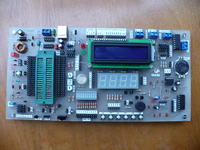 http://tnij.org/syp3 http://tnij.org/syp3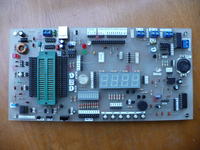 http://tnij.org/syp6 http://tnij.org/syp6soon present details on the forum Regards |
|
|
|
« Last Edit: October 27, 2012, 02:17:59 14:17 by blue_17 »
|
Logged
|
|
|
|
~5
Newbie
Offline
Posts: 7
Thank You
-Given: 14
-Receive: 0
|
|
« Reply #19 on: October 27, 2012, 04:19:21 16:19 » |
|
Yes but my board is in Eagle format Fair point. To be honest, I'm surprised they released the project in Rhino format instead Eagle. |
|
|
|
|
Logged
|
|
|
|
~5
Newbie
Offline
Posts: 7
Thank You
-Given: 14
-Receive: 0
|
|
« Reply #20 on: November 07, 2012, 06:08:10 18:08 » |
|
(...)
Yes in my PCB USB port is only for power supply.
(...)
I don't know if it is of any interest but I discovered this. The USB is implemented via firmware (no USB driver required). As far as I can understand, it also requires a change in the Adruino IDE configuration file but apart from that, it shouldn't require anything else. It might be intersting add the functionality to your board, it requires only 2 diodes and a few resistors. |
|
|
|
|
Logged
|
|
|
|
Gallymimu
Hero Member
Offline
Posts: 704
Thank You
-Given: 152
-Receive: 214
|
|
« Reply #21 on: November 08, 2012, 03:03:16 15:03 » |
|
I don't know if it is of any interest but I discovered this. The USB is implemented via firmware (no USB driver required). As far as I can understand, it also requires a change in the Adruino IDE configuration file but apart from that, it shouldn't require anything else. It might be intersting add the functionality to your board, it requires only 2 diodes and a few resistors. according to this site: http://www.atmel.com/devices/atmega168.aspxThe ATMEGA168 used in this metaboard project doesn't have a USB hardware port. I don't see how this could work without a USB transceiver. Am I misunderstanding the project? |
|
|
|
|
Logged
|
|
|
|
Alex5532
Inactive
Offline
Posts: 5
Thank You
-Given: 9
-Receive: 36
|
|
« Reply #22 on: November 08, 2012, 05:20:10 17:20 » |
|
@Gallymimu I suppose that the Metaboard use V-USB, you can fine more information at http://www.obdev.at/products/vusb/index.htmlAlex |
|
|
|
« Last Edit: November 08, 2012, 05:26:15 17:26 by Alex5532 »
|
Logged
|
|
|
|
~5
Newbie
Offline
Posts: 7
Thank You
-Given: 14
-Receive: 0
|
|
« Reply #23 on: November 08, 2012, 06:07:07 18:07 » |
|
I think it is exacly what it does. There is another board (MHVBoard) that does something similar. My understanding is that it very similar to the Mataboard but it has some extra funcionality (e.g. +3.3V out) |
|
|
|
|
Logged
|
|
|
|
|


