sphinx
Hero Member

 Offline Offline
Posts: 915
Thank You
-Given: 607
-Receive: 265
|
 |
« on: March 16, 2024, 06:43:55 18:43 » |
|
i know it might not be the place to ask for input on building an audio amplifier
i just didnt want to join some other forum for just this subject
i am looking for a fairly good not too simple in design
here are my sort of guide lines
this will be built with components from non alibaba or similar sellers
more like digikey mouser
300-500 euros/dollars
a good and solid design with a bit of reserve power and to be longish lasting
i want to build something together pre-amp but this is just for the power-amp
no displays or any mcu in this just as simple as is need to be not not like
modern amp with advanced displays, since this will be a 2-channel amp
100w in 8ohm
the semiconductors from readily available stock and not any abscure expensive ones
easy to find ones
low noise(nothing extreme the best i can for mentoined price)
good bandwith i think this not that difficult to achieve with modern components
with dc check realy and maybe some other protection thats good to have
i am not sure what more to ask for.
thanks in advance
|
|
|
|
|
 Logged
|
laws of physics are not laws at all, just assumptions and formulas that work as long as we don't figure something new that wrecks the calculations. the infinite onion try to peel that one
|
|
|
enzine
Junior Member
Offline
Posts: 83
Thank You
-Given: 649
-Receive: 57
|
|
« Reply #1 on: March 17, 2024, 06:37:37 18:37 » |
|
In 1984 I built and used for many years the famous "Crescendo" amplifier published by Elektor in 1982. Some of my friends still use it with great satisfaction. Excellent sound, great dynamics, easily available components are just some of the advantages of this workhorse of homemade HiFi. Recently (2001) Elektor published the "Crescendo Millenium Edition". I recommend you start with this project. https://www.elektormagazine.com/magazine/elektor-198212/44973https://www.elektormagazine.com/magazine/elektor-200104/16985Ciao Enzo |
|
|
|
« Last Edit: March 17, 2024, 06:50:05 18:50 by enzine »
|
Logged
|
|
|
|
optikon
Cracking Team
Hero Member
Offline
Posts: 849
Thank You
-Given: 1092
-Receive: 2002
|
|
« Reply #2 on: March 18, 2024, 12:42:05 00:42 » |
|
Any reason buying one cannot work for you?
|
|
|
|
|
Logged
|
I can explain this to you. I can't comprehend it for you.
|
|
|
sphinx
Hero Member
Offline
Posts: 915
Thank You
-Given: 607
-Receive: 265
|
|
« Reply #3 on: March 18, 2024, 02:04:12 02:04 » |
|
i do not want anything without schematics
nothing with any mcu/firmware/displays
something that has a calculated lifespan built in
no obscure components that cant buy
no markings made by the manufacturers on components
|
|
|
|
|
Logged
|
laws of physics are not laws at all, just assumptions and formulas that work as long as we don't figure something new that wrecks the calculations. the infinite onion try to peel that one
|
|
|
Sideshow Bob
Cracking Team
Hero Member
Offline
Posts: 985
Thank You
-Given: 230
-Receive: 961
|
|
« Reply #4 on: March 18, 2024, 09:55:38 09:55 » |
|
How will you attack this. Like will you go class D or a more traditional way class A/B. Linear or Switch Mode PSU? Another interesting topic may be the housing. As a power amplifiers are built around the heatsinks. Perhaps it could be an idea to source a non working 100W (ish) power amplifier locally. And use that as a base. Most likely the output stage will be blown. But the transformer will probably be OK(the transformer will be condiserable part of the total cost). It is just an idea and I do not know how viable this is for you.
|
|
|
|
|
Logged
|
I have come here to chew bubblegum and kick ass... and I'm all out of bubblegum
|
|
|
sphinx
Hero Member
Offline
Posts: 915
Thank You
-Given: 607
-Receive: 265
|
|
« Reply #5 on: March 18, 2024, 12:00:00 12:00 » |
|
i have two chassis i can use on the biggish side
i also have a big heatsink i could cut in 2 pieces
i will use a/b type amplifier
not yet sure about power supply
the onkyo Onkyo TX-SV 727 R i have got bad i will see if i can fix it and recap it, its the first time i got issues with it
it has not been fixed/repaierd before, if not i will build something
i very rarely went above 50% on the volume
just for fun i looked for the power transistor for the onkyo 2sc3281 and 2sa1302
i was looking to see prices for those and on alibaba 10 pairs for 60$ sounds a bit too low
and looking at the pictures i could seen they been sandblasted as the little dimples are also blasted as well
on ebay i saw some where they were dirty and not clean so there is something fishy going on
so no asia bying for me
|
|
|
|
« Last Edit: March 18, 2024, 12:53:00 12:53 by sphinx »
|
Logged
|
laws of physics are not laws at all, just assumptions and formulas that work as long as we don't figure something new that wrecks the calculations. the infinite onion try to peel that one
|
|
|
PM3295
Senior Member
Offline
Posts: 279
Thank You
-Given: 340
-Receive: 132
|
|
« Reply #6 on: March 18, 2024, 05:09:28 17:09 » |
|
just for fun i looked for the power transistor for the onkyo 2sc3281 and 2sa1302
i was looking to see prices for those and on alibaba 10 pairs for 60$ sounds a bit too low
and looking at the pictures i could seen they been sandblasted as the little dimples are also blasted as well
on ebay i saw some where they were dirty and not clean so there is something fishy going on
so no asia bying for me
From my experience, most of the older or expensive power transistors from these budget sites are fake remarked parts. |
|
|
|
|
Logged
|
|
|
|
optikon
Cracking Team
Hero Member
Offline
Posts: 849
Thank You
-Given: 1092
-Receive: 2002
|
|
« Reply #7 on: March 19, 2024, 01:25:43 01:25 » |
|
You said you could spend $500 so I think it can be done for that, no need to buy from grey markets / e-pray
There are gobs of reference amplifiers (schematics) on the web, grab one, update it with your part choices, simulate it, then build it.
|
|
|
|
|
Logged
|
I can explain this to you. I can't comprehend it for you.
|
|
|
Sideshow Bob
Cracking Team
Hero Member
Offline
Posts: 985
Thank You
-Given: 230
-Receive: 961
|
|
« Reply #8 on: March 19, 2024, 11:35:04 11:35 » |
|
The problem is that it may be difficult to source some components. I looked at the 2001 version and even here it hard to get most of the transistors. Like 2SK537, 2SK1530, 2SJ201 From what I have found. 2SK1530/2SJ201 ->IRFP240PBF/IRFP9240PBF also 2SK537 -> 2SK1643/2SK1338/2SK2733 But non of these SKUs is available from mouser(or similar) |
|
|
|
« Last Edit: March 20, 2024, 04:53:20 16:53 by Sideshow Bob »
|
Logged
|
I have come here to chew bubblegum and kick ass... and I'm all out of bubblegum
|
|
|
kumar
Junior Member
Offline
Posts: 68
Thank You
-Given: 14
-Receive: 169
|
|
« Reply #9 on: March 19, 2024, 12:48:28 12:48 » |
|
insted of the output mosfet, 2SK537 ,
2SK1530 ,i used BUZ901,BUZ906 without any issues
|
|
|
|
|
Logged
|
|
|
|
enzine
Junior Member
Offline
Posts: 83
Thank You
-Given: 649
-Receive: 57
|
|
« Reply #10 on: March 19, 2024, 02:49:07 14:49 » |
|
The problem is that it may be difficult to source some components. I looked at the 2001 and even here it hard to get most of the transistors what. Like 2SK537, 2SK1530, 2SJ201
From what I have found.
2SK1530/2SJ201 ->IRFP240PBF/IRFP240PBF
also
2SK537 -> 2SK1643/2SK1338/2SK2733 But non of these SKUs is available from mouser(or similar)
You're right, I bought them from a well-known and reliable distributor of electronic components. Only now have I realized that more than 10 years have passed  . "Fugit irreparabile tempus"Ciao Enzo |
|
|
|
|
Logged
|
|
|
|
PM3295
Senior Member
Offline
Posts: 279
Thank You
-Given: 340
-Receive: 132
|
|
« Reply #11 on: March 19, 2024, 05:52:34 17:52 » |
|
Try get hold of a copy of the book "Designing Audio Power Amplifiers 2019" by Bob Cordell. He walks you through a complete design, with the theory, calculations, simulations and measurements from the input through to the output stage. He starts with a basic design and goes through steps to lower the %THD, depending how complicated you want this to be. Years ago, having a %THD of 0.1% was considered to be Hi-Fi quality. Bob shows how you can lower this figure by many orders of magnitude by analyzing the parts responsible for causing distortion and how to improve it. It is a really good read. The parts he used in his designs should still be readily available.
Alternatively you could also look for books on audio amplifier design by Douglas Self. Both are worth reading.
|
|
|
|
« Last Edit: March 19, 2024, 06:00:35 18:00 by PM3295 »
|
Logged
|
|
|
|
sphinx
Hero Member
Offline
Posts: 915
Thank You
-Given: 607
-Receive: 265
|
|
« Reply #12 on: March 20, 2024, 01:10:01 01:10 » |
|
a got the 2006 ed of the book mentioned and some other books
by Douglas Self. i wasn't exactly looking for designing myself
but i will check out the books i borrowed from the internet libraru.
|
|
|
|
|
Logged
|
laws of physics are not laws at all, just assumptions and formulas that work as long as we don't figure something new that wrecks the calculations. the infinite onion try to peel that one
|
|
|
PM3295
Senior Member
Offline
Posts: 279
Thank You
-Given: 340
-Receive: 132
|
|
« Reply #13 on: March 20, 2024, 05:17:48 05:17 » |
|
You can always just build up one of Bob's designs without doing any design yourself. You will have to make your own pcb design to suit your enclosure, panel layout, etc. The advantage will be having an in depth description of the circuit operation if you need to do some troubleshooting after the build or later in use when something breaks down.
|
|
|
|
« Last Edit: March 20, 2024, 05:25:08 05:25 by PM3295 »
|
Logged
|
|
|
|
Sideshow Bob
Cracking Team
Hero Member
Offline
Posts: 985
Thank You
-Given: 230
-Receive: 961
|
|
« Reply #14 on: March 20, 2024, 09:38:17 09:38 » |
|
insted of the output mosfet, 2SK537 ,
2SK1530 ,i used BUZ901,BUZ906 without any issues
You meant did you not? 2SK1530= BUZ901 N Channel, 200 V, 8 A, 1.5 ohm 2SJ201= BUZ906 P Channel, 200 V, 8 A, 1.4 ohm But what did you use for the 2SK537 N -Channel 1A mosfet? |
|
|
|
« Last Edit: March 20, 2024, 11:23:26 11:23 by Sideshow Bob »
|
Logged
|
I have come here to chew bubblegum and kick ass... and I'm all out of bubblegum
|
|
|
kumar
Junior Member
Offline
Posts: 68
Thank You
-Given: 14
-Receive: 169
|
|
« Reply #15 on: March 21, 2024, 02:50:03 02:50 » |
|
You meant did you not?
2SK1530= BUZ901 N Channel, 200 V, 8 A, 1.5 ohm
2SJ201= BUZ906 P Channel, 200 V, 8 A, 1.4 ohm
But what did you use for the 2SK537 N -Channel 1A mosfet?
sllidshow Bob,what he said is obsolutely correct.BUZ901 and BUZ906 is used as output pair. in 1982's Elektor crescendo article,1984's Elektor mini crescendo article they were not used any transistor for quiescent current circuit. but elektor crescendo millenium Edition, they used 2SK537 in quiescent current circuit. |
|
|
|
|
Logged
|
|
|
|
Catcatcat
Senior Member
Offline
Posts: 416
Thank You
-Given: 278
-Receive: 1536

|
|
« Reply #16 on: March 21, 2024, 11:05:12 11:05 » |
|
I discovered this Chinese manufacturer https://en.viva-elec.com.tw/stereo-2023.htmlI designed a simple amplifier for myself, I plan to order production this month.   |
|
|
|
|
Logged
|
|
|
|
Sideshow Bob
Cracking Team
Hero Member
Offline
Posts: 985
Thank You
-Given: 230
-Receive: 961
|
|
« Reply #17 on: March 21, 2024, 12:44:54 12:44 » |
|
Is it your design? Maybe what I would have done is do add holes for some for some machine screws to secure and ensure good contact with the IC and the heatsink. It should be easy to a drill tap on the heatsink. To get the holes on the heatsink aligned. Just print out the PCB on paper in size 1:1 and use that as a template. Also if you use say 3mm machine screws use a slightly bigger hole say 4mm. And create a keepout era for copper around the holes |
|
|
|
|
Logged
|
I have come here to chew bubblegum and kick ass... and I'm all out of bubblegum
|
|
|
Catcatcat
Senior Member
Offline
Posts: 416
Thank You
-Given: 278
-Receive: 1536
|
|
« Reply #18 on: March 21, 2024, 06:07:22 18:07 » |
|
I've thought about it, but I plan to just stick it on. I want to test how it performs.
|
|
|
|
|
Logged
|
|
|
|
Sideshow Bob
Cracking Team
Hero Member
Offline
Posts: 985
Thank You
-Given: 230
-Receive: 961
|
|
« Reply #19 on: March 21, 2024, 06:40:18 18:40 » |
|
I've thought about it, but I plan to just stick it on. I want to test how it performs.
Just for testing you could use thermally conductive adhesive tape. But I suspect if they have a recommenced heat sink it will be somewhat undermentioned. Anyway how do you order these Ics? I have for a long time wanted to build a class D amplifier. Ics from Texas Instruments are available at many trusted component outlets |
|
|
|
|
Logged
|
I have come here to chew bubblegum and kick ass... and I'm all out of bubblegum
|
|
|
Catcatcat
Senior Member
Offline
Posts: 416
Thank You
-Given: 278
-Receive: 1536
|
|
« Reply #20 on: March 21, 2024, 07:04:43 19:04 » |
|
I order printed circuit boards and assembly completely from jlcpcb. I really like this option. I've done it many times, it always comes, I turn it on and everything works. In December I made a development board for myself with MCU PIC18F47Q84 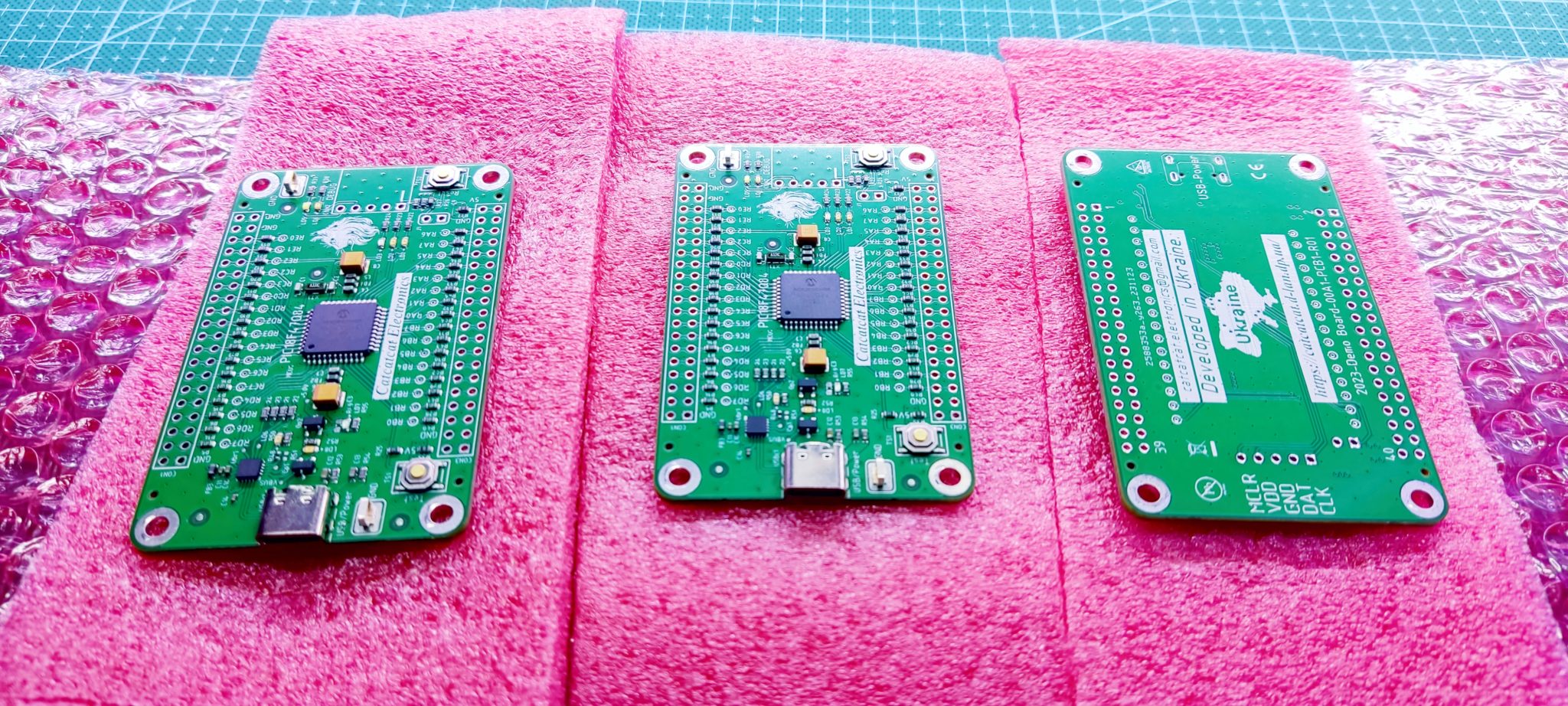
|
|
|
|
|
Logged
|
|
|
|
fluxface
Inactive
 Warned
Offline Warned
Offline
Posts: 2
Thank You
-Given: 5
-Receive: 7
|
|
« Reply #21 on: March 22, 2024, 12:04:23 12:04 » |
|
I order printed circuit boards and assembly completely from jlcpcb. I really like this option. I've done it many times, it always comes, I turn it on and everything works.
In December I made a development board for myself with MCU PIC18F47Q84
How long did jlcpcb take for assembly? I usually use PCBWay for bare boards, which have always been excellent. |
|
|
|
|
Logged
|
|
|
|
Catcatcat
Senior Member
Offline
Posts: 416
Thank You
-Given: 278
-Receive: 1536
|
|
« Reply #22 on: March 22, 2024, 12:15:05 12:15 » |
|
Assembly usually takes no more than 1-2 days. This is the time from ordering the PCB itself to the moment of complete assembly.  |
|
|
|
|
Logged
|
|
|
|
Sideshow Bob
Cracking Team
Hero Member
Offline
Posts: 985
Thank You
-Given: 230
-Receive: 961
|
|
« Reply #23 on: March 23, 2024, 11:16:58 11:16 » |
|
Assembly usually takes no more than 1-2 days.
This is the time from ordering the PCB itself to the moment of complete assembly.
Did you add some extra output filters etc, or did you just follow the Typical Application from the data sheet. Also it could be interesting to hear how it sounds |
|
|
|
|
Logged
|
I have come here to chew bubblegum and kick ass... and I'm all out of bubblegum
|
|
|
Catcatcat
Senior Member
Offline
Posts: 416
Thank You
-Given: 278
-Receive: 1536
|
|
« Reply #24 on: March 24, 2024, 08:17:02 08:17 » |
|
In this project, I want to assemble according to the circuit offered by the manufacturer and test the audio amplifier chip itself. I'm still making some changes to the project. If you are interested, I can inform you how the process of ordering, manufacturing and testing an audio amplifier will go.  |
|
|
|
|
Logged
|
|
|
|
sphinx
Hero Member
Offline
Posts: 915
Thank You
-Given: 607
-Receive: 265
|
|
« Reply #25 on: March 29, 2024, 07:51:15 19:51 » |
|
i am here sharing a reversed eng. pcb from the pdf document
file
1
both copied layers are the same one copied to the other the pads are separately added
2
top layer from file 1, bottom layer is remade from top layer
3
amplifier
4
pcb 2
pplease be aware this is the first time im was trying rev. eng
i wasnt in trying to modify the "scanned" layer i do not know why
but i could delete layer from tp overlay but no modifications
since i set the clearnce to -1 to be able to route between ads since there is no netlist
i cant check if there are any issues with clearance.
al made with latest altium designer
|
|
|
|
« Last Edit: March 29, 2024, 07:59:00 19:59 by sphinx »
|
Logged
|
laws of physics are not laws at all, just assumptions and formulas that work as long as we don't figure something new that wrecks the calculations. the infinite onion try to peel that one
|
|
|
Sideshow Bob
Cracking Team
Hero Member
Offline
Posts: 985
Thank You
-Given: 230
-Receive: 961
|
|
« Reply #26 on: March 30, 2024, 11:05:19 11:05 » |
|
i am here sharing a reversed eng. pcb from the pdf document
What was your process? And also how do plan to source the the MOSFET transistors. At least 2SK537 can be somewhat tricky to get. Not impossible though |
|
|
|
|
Logged
|
I have come here to chew bubblegum and kick ass... and I'm all out of bubblegum
|
|
|
sphinx
Hero Member
Offline
Posts: 915
Thank You
-Given: 607
-Receive: 265
|
|
« Reply #27 on: March 30, 2024, 02:31:43 14:31 » |
|
first i deleted the unessesary stuff in photoshot and only had the pcb info
i then cropped out the the two parts tracks in one the rest with placement info
selected the layer where i wanted to import to
then i saved them to svg format and rightclicked on pcb selected placement and selected graphics, selected an are of similar size
when trying svg format i had issues with ragged edges i then tried png and reoslution got better
the i scaled it by selecting all and then right click select unions and then click resize unions
then click on the imported and and white dots apperar pulling them changes the scale
(for some reason i wasa not able to edit the imported stuff)
to be able to connect between pads without a netlist one needs to set cleareance to -1
then create/route/copy the new tracks and polygons on another layer
when importing top overlay parts it seemed to wrk even if there was some greyscaled part in it
it seems that AD likes white and black (dont know much about this)
i am going to try repair my onkyo before building something, i just wanted to try this method of
rev eng of making a pcb so that whay i made this
|
|
|
|
|
Logged
|
laws of physics are not laws at all, just assumptions and formulas that work as long as we don't figure something new that wrecks the calculations. the infinite onion try to peel that one
|
|
|
Sideshow Bob
Cracking Team
Hero Member
Offline
Posts: 985
Thank You
-Given: 230
-Receive: 961
|
|
« Reply #28 on: April 01, 2024, 04:40:12 16:40 » |
|
I am going to try repair my onkyo before building something, i just wanted to try this method of
rev eng of making a pcb so that whay i made this
If you find the Gerber file for this design. You could try reverse engineer using this method. https://www.youtube.com/watch?v=j3MgdCoAoiUThe Gerber file can be downloaded from Elektor. But that requires paid membership (Green or Gold) I am working recreating the schematics. I am almost done with amp part |
|
|
|
|
Logged
|
I have come here to chew bubblegum and kick ass... and I'm all out of bubblegum
|
|
|
sphinx
Hero Member
Offline
Posts: 915
Thank You
-Given: 607
-Receive: 265
|
|
« Reply #29 on: April 01, 2024, 06:38:44 18:38 » |
|
here are the gerbers, to me those look a bit weird compare to those mae with ad
i git some issues using those in ad
|
|
|
|
« Last Edit: April 01, 2024, 07:29:29 19:29 by sphinx »
|
Logged
|
laws of physics are not laws at all, just assumptions and formulas that work as long as we don't figure something new that wrecks the calculations. the infinite onion try to peel that one
|
|
|
sphinx
Hero Member
Offline
Posts: 915
Thank You
-Given: 607
-Receive: 265
|
|
« Reply #30 on: April 02, 2024, 04:40:10 16:40 » |
|
If you find the Gerber file for this design. You could try reverse engineer using this method. https://www.youtube.com/watch?v=j3MgdCoAoiUThe Gerber file can be downloaded from Elektor. But that requires paid membership (Green or Gold) I am working recreating the schematics. I am almost done with amp part did you get the gerber files to work ? |
|
|
|
|
Logged
|
laws of physics are not laws at all, just assumptions and formulas that work as long as we don't figure something new that wrecks the calculations. the infinite onion try to peel that one
|
|
|
Sideshow Bob
Cracking Team
Hero Member
Offline
Posts: 985
Thank You
-Given: 230
-Receive: 961
|
|
« Reply #31 on: April 02, 2024, 06:22:11 18:22 » |
|
did you get the gerber files to work ?
Well yes or no I got them to work partly. The aperture values was 10 times to big. But using the unit tenths(1/10000 inch) all worked perfectly. The drl file has also the same problem. Everything is then times bigger than it should |
|
|
|
|
Logged
|
I have come here to chew bubblegum and kick ass... and I'm all out of bubblegum
|
|
|
sphinx
Hero Member
Offline
Posts: 915
Thank You
-Given: 607
-Receive: 265
|
|
« Reply #32 on: April 02, 2024, 06:46:29 18:46 » |
|
that looks he(two hockeysyicks) of alot better than to thoe i looked at from the original files, i did a lot of work unessesary
but i still pretty much a newb with pcb design, no i need to figure out what aperture is and what it does.
can you just explain wht is the difference between G0 and G2 file they look kinda the same
and i am going to get gerbview to see what it can do, seen it but not used it
G0 G2 one of those is bottom overlay and the other one is the drill file is my guess
|
|
|
|
« Last Edit: April 02, 2024, 07:33:17 19:33 by sphinx »
|
Logged
|
laws of physics are not laws at all, just assumptions and formulas that work as long as we don't figure something new that wrecks the calculations. the infinite onion try to peel that one
|
|
|
sphinx
Hero Member
Offline
Posts: 915
Thank You
-Given: 607
-Receive: 265
|
|
« Reply #33 on: April 03, 2024, 10:30:23 22:30 » |
|
i trying to make a netlist i got so far, i am get"Netlist extraction error: no tools defined in NC tools table. Please define the tools before proceeding." seems to be the drill file but whatever i choose i cant come past this one any suggestions just for s n giggles i change d the layers to solder paste layer and i got past the error now got i netlist but i think a drill file is needed or this needs to be done manually place pads at least i can export to pcb since this is the first time doing in am really not sure what i am doing but i a couple of days i will be a suppa duppa mastah on rev eng  i am attaching the files i got so far i just renamed the file so i could remember which one was what the issues i got now is that i got only top and bottom layear but i see the top overlay but its not shown, gotta figure out this one now i tried to export and then import the layers but this did not work it just added the layers i manually added but still not showing all other layers i think i messed up on this one seems the board is like .4 x .56 inches big and to my knowledge there are no miniature cmponents on this board back to the drawing board |
|
|
|
« Last Edit: April 04, 2024, 12:51:33 00:51 by sphinx »
|
Logged
|
laws of physics are not laws at all, just assumptions and formulas that work as long as we don't figure something new that wrecks the calculations. the infinite onion try to peel that one
|
|
|
Flex
Junior Member
Offline
Posts: 72
Thank You
-Given: 167
-Receive: 127
|
|
« Reply #34 on: April 04, 2024, 06:38:23 06:38 » |
|
May be this website will provide maximum support for designing Audio system with various projects since 2001 Welcome to ESP, the home of DIY audio and electronics articles, and PCBs for popular projects. Electronics is a wonderful hobby, and with DIY there is a huge scope to get the best performance for less money than otherwise. DIY is fun and educational, and by building your own audio equipment, you get to learn electronics as well as build equipment that may cost a great deal more in the shops. ESP is committed to providing high quality projects that are known to work, printed circuit boards (PCBs) for the most popular projects, and to assist you if necessary to complete or debug your project. There is a very wide range of power amplifiers, preamps, guitar/ bass amplifiers, studio equipment, effects, and other projects to build, including loudspeakers, subwoofers, and many others. https://sound-au.com/index.html |
|
|
|
|
Logged
|
|
|
|
sphinx
Hero Member
Offline
Posts: 915
Thank You
-Given: 607
-Receive: 265
|
|
« Reply #35 on: April 06, 2024, 10:36:05 10:36 » |
|
this what i get when importi the drill file
|
|
|
|
|
Logged
|
laws of physics are not laws at all, just assumptions and formulas that work as long as we don't figure something new that wrecks the calculations. the infinite onion try to peel that one
|
|
|
Sideshow Bob
Cracking Team
Hero Member
Offline
Posts: 985
Thank You
-Given: 230
-Receive: 961
|
|
« Reply #36 on: April 06, 2024, 11:08:47 11:08 » |
|
this what i get when importi the drill file
This file should work. At the time of importing. You MUST check the units. Camtastic if full of bugs and this is one of them. So the units dialog you should use is this Digits 3:4 Units Metric Zero Supression None Type Absolut |
|
|
|
|
Logged
|
I have come here to chew bubblegum and kick ass... and I'm all out of bubblegum
|
|
|
sphinx
Hero Member
Offline
Posts: 915
Thank You
-Given: 607
-Receive: 265
|
|
« Reply #37 on: April 06, 2024, 11:30:27 11:30 » |
|
new screenshot
|
|
|
|
|
Logged
|
laws of physics are not laws at all, just assumptions and formulas that work as long as we don't figure something new that wrecks the calculations. the infinite onion try to peel that one
|
|
|
Sideshow Bob
Cracking Team
Hero Member
Offline
Posts: 985
Thank You
-Given: 230
-Receive: 961
|
|
« Reply #38 on: April 06, 2024, 12:50:27 12:50 » |
|
new screenshot
Close but no cigar I would say  Well in this case the Gerber files is in English units The settings are 2:3 English Absolute none When importing you can select several files as long as the setting is the same So go to tables->Layers and do this and tables->Layers Order and do this (think about it looking at the PCB from above) First at this point you will be able to extract the netlist |
|
|
|
|
Logged
|
I have come here to chew bubblegum and kick ass... and I'm all out of bubblegum
|
|
|
sphinx
Hero Member
Offline
Posts: 915
Thank You
-Given: 607
-Receive: 265
|
|
« Reply #39 on: April 07, 2024, 01:45:42 01:45 » |
|
no matter on what i try i get the same results with a .4' x .5" size
the drill seems to be the right i measured and there are 100mils between the ic pad drills
well i have gotten the files using my first try with netlist and so am satisfied with
those, i never fiddled with gerbers before so this is all not famliar to me
|
|
|
|
|
Logged
|
laws of physics are not laws at all, just assumptions and formulas that work as long as we don't figure something new that wrecks the calculations. the infinite onion try to peel that one
|
|
|
Sideshow Bob
Cracking Team
Hero Member
Offline
Posts: 985
Thank You
-Given: 230
-Receive: 961
|
|
« Reply #40 on: April 07, 2024, 04:36:33 16:36 » |
|
 no matter on what i try i get the same results with a .4' x .5" size
the drill seems to be the right i measured and there are 100mils between the ic pad drills
well i have gotten the files using my first try with netlist and so am satisfied with
those, i never fiddled with gerbers before so this is all not famliar to me
It turns out it was I who goofed up badly, By sending files with the wrong scaling. I feel ashamed . They was from early in the process and at that that point since well they looked good. I assumed they was correct. You must be a nitpick when dealing with this. measure twice cut once. See the rar file and the readme.txt file. In the rar file I have also included a schematic of the amp. It is very early in the process. And it is a total mess regarding values,ref_des, and pkg_types. Only the symbols is correct. But it is a start Edit if you wonder where I found the Gerber data it was from the .rep file. They will change for every project of course Edit_2 If any want to know the video is https://www.youtube.com/watch?v=j3MgdCoAoiU. Also note the process du not understand that all the square pads actually are pads. And just omit these these as drilled holes/pads
|
|
|
|
« Last Edit: April 07, 2024, 04:57:10 16:57 by Sideshow Bob »
|
Logged
|
I have come here to chew bubblegum and kick ass... and I'm all out of bubblegum
|
|
|
sphinx
Hero Member
Offline
Posts: 915
Thank You
-Given: 607
-Receive: 265
|
|
« Reply #41 on: April 08, 2024, 12:12:00 00:12 » |
|
When i learned a tiny bit more about gerbers i started to realize the size and not matter what i did i just couldnt get em to fit.
I know i have a tiny bit of ocd, but this wasnt about that it was about the difference in size, since my knowlegde of gerber is far
behind newb so not figuring out why they did size didnt match, no matter of what i did they just wouldnt match. So thats why
i gave up.
|
|
|
|
|
Logged
|
laws of physics are not laws at all, just assumptions and formulas that work as long as we don't figure something new that wrecks the calculations. the infinite onion try to peel that one
|
|
|
sphinx
Hero Member
Offline
Posts: 915
Thank You
-Given: 607
-Receive: 265
|
|
« Reply #42 on: April 08, 2024, 09:18:12 09:18 » |
|
i am here sharing all the files about crescendo millenium all done in AD_24.3.1
there are 5 folders
crescendo millennium
this where it all started with importing of files into pcb
crescendo millennium from gerbers
this where all the work was done and is those that are the latest
crescendo millennium from gerbers cam
here there was scaling issues from gerber files not to be used
crescendo millennium from gerbers pb
here is the tiny protection board made separately since there was not many komponents here
crescendo millennium from gerbers zsb
files made by SideShowBob only the schematics.
have fun with it
/sphinx
|
|
|
|
|
Logged
|
laws of physics are not laws at all, just assumptions and formulas that work as long as we don't figure something new that wrecks the calculations. the infinite onion try to peel that one
|
|
|
|


